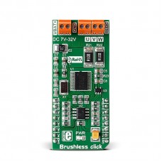
Brushless click
Brushless click carries Toshiba's TB6575FNG IC for driving 3-phase full-wave Brushless DC motors — which are ideal for powering flying drones. The click is able to safely drive external motors with up to 32V/2A.
The board features three pairs of onboard screw terminals. VBAT is for connecting an external 7-32V DC power supply. The other two are for connecting an external motor.
Precision control
Brushless motors have a very long operating life and can be precisely controlled – the speed is adjusted by the amount of input voltage (higher voltage equals more speed).
The TB6575FNG IC controls the rotation speed by changing the PWM duty cycle.
MOSFET chips
Two types of MOSFET chips on board switch the output on and off. This controls the voltage levels applied to the motor which in turn determines the speed and rotation of the motor shaft.
Brushless click communicates with the target board MCU over the PWM pin, as well as INT, AN and RST pins. The board is designed to use a 5V power supply only. See the documentation page for more details.
Brushless click is theoretically capable of outputting higher currents, however, in such a case the MOSFET chips have to be cooled down with an external cooler.
Applications
Automotive industry, drones (because of the good power-to weight ratio of brushless motors), computers, medical equipment, HVAC systems, small home appliances, robotics, battery powered systems, small cooling fans in computers, toys, etc.
Specifications
| Type | DC |
| Applications | Automotive industry, drones (because of the good power-to weight ratio of brushless motors), computers, medical equipment, HVAC systems, small home appliances, robotics, battery powered systems, small cooling fans in computers, toys, etc. |
| On-board modules | Toshiba's TB6575FNG IC |
| Key Features | MOSFET chips toggle the output on and off, MCP6281 prevents phase reversal |
| Key Benefits | Overcurrent protection, Forward/reverse rotation |
| Interface | GPIO,PWM |
| Input Voltage | 5V,5V |
| Compatibility | mikroBUS |
| Click board size | L (57.15 x 25.4 mm) |
Motor position detection error
Position detection is synchronized with the PWM signal generated in the IC. When the IC is used in a high speed motor a position detection error relative to the PWM frequency may occur. The detection is performed on the falling edge of the PWM signal. An error is recognized when the pin voltage exceeds the reference voltage.
Pinout diagram
This table shows how the pinout on Brushless click corresponds to the pinout on the mikroBUS™ socket (the latter shown in the two middle columns).
Programming
This code snippet initializes required ports, ADC channels and PWM module. It also initializes TFT and sets motor direction. In an endless loop, if button is pressed, we increment or decrement current PWM duty by STEP, which consequently change the rotating speed of BLDC motor.
Code example
Code examples for Brushless click, written for MikroElektronika hardware and compilers are available on Libstock.
1 void main()
2 {
3  MCU_Init();
4  TFT_Init_ILI9341_8bit(320, 240);  // TFT Init
5   TFT_BLED = 1;
6   DrawFrame();
7   MOTOR_DIR = CCW;  // Setting motor direction to counter-clock-wise
8   while(1) {
9     if (GPIOD_IDR.B3) {                // button on PD3 pressed
10       Delay_ms(10);
11       current_speed = current_speed + STEP;   // increment current_duty
12       if (current_speed > pwm_period)       // if we increase current_duty greater then possible pwm_period value
13       {
14         current_speed = 0;                    // reset current_duty value to zero
15       }
16       PWM_TIM5_Set_Duty(current_speed,  _PWM_NON_INVERTED, _PWM_CHANNEL1);  // set newly acquired duty ratio
17      }
18     if (GPIOD_IDR.B6) {                // button on PD6 pressed
19       Delay_ms(10);
20       current_speed = current_speed - STEP;
21       if (current_speed > pwm_period)       // if we decrease current_duty greater then possible pwm_period value (overflow)
22       {
23           current_speed = pwm_period;          // set current_duty to value of pwm_period
24       }
25       PWM_TIM5_Set_Duty(current_speed,  _PWM_NON_INVERTED, _PWM_CHANNEL1); // set newly acquired duty ratio
26      }
27     Delay_ms(20);
28    // current_speed display
29     WordToStr(current_speed, txt);
30     TFT_Rectangle(150, 80, 250, 110);
31     TFT_Write_Text(txt, 150, 80);
32   }
33 }
Downloads
mikroBUS™ Standard specificationEnter the code in the box below:


