CAN Isolator click
Product Code: MIKROE-2627


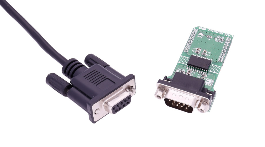
The click carries a DB 9-pin male connector.
ADM3053 features
The ADM3053 is an isolated controller area network (CAN) physical layer transceiver with an integrated isolated DC-to-DC converter.
The ADM3053 creates a fully isolated interface between the CAN protocol controller and the physical layer bus. It is capable of running at data rates of up to 1 Mbps.
Connector features
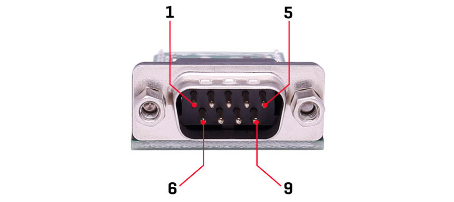
This is a standard DB 9-pin male connector.
Specifications
| Type | CAN,Isolator |
| Applications | CAN data buses, Industrial field networks |
| On-board modules | ADM3053 CAN transceiver, DB 9-pin connector |
| Key Benefits | No need for an external supply for the isolated side |
| Interface | UART |
| Input Voltage | 3.3V or 5V |
| Compatibility | mikroBUS |
| Click board size | L (57.15 x 25.4 mm) |
Pinout diagram
This table shows how the pinout on CAN Isolator click corresponds to the pinout on the mikroBUS™ socket (the latter shown in the two middle columns).
| Notes | Pin | Pin | Notes | ||||
|---|---|---|---|---|---|---|---|
| NC | 1 | AN | PWM | 16 | NC | ||
| NC | 2 | RST | INT | 15 | NC | ||
| NC | 3 | CS | TX | 14 | RXD | Receiver Output Data | |
| NC | 4 | SCK | RX | 13 | TXD | Driver Input Data | |
| NC | 5 | MISO | SCL | 12 | NC | ||
| NC | 6 | MOSI | SDA | 11 | NC | ||
| Power supply | +3.3V | 7 | 3.3V | 5V | 10 | +5V | Power supply |
| Ground | GND | 8 | GND | GND | 9 | GND | Ground |
Jumpers and settings
| Designator | Name | Default Position | Default Option | Description |
|---|---|---|---|---|
| JP1 | VIO.SEL. | Left | 3V3 | Power Supply Voltage Selection 3V3/5V, left position 3V3, right position 5V |
| JP2 | SLOPE SEL | Left | HI | Slope select, default high rate, right option the slope is limited |
Programming
Code snippet
Example of CAN confgiration - PIC32
01 // set required baud rate and sampling rules
02 unsigned int can_config_flags;
03 CAN1SetOperationMode(_CAN_MODE_CONFIG,0xFF);
04 can_config_flags = _CAN_CONFIG_SAMPLE_THRICE &
05                    _CAN_CONFIG_PHSEG2_PRG_ON &
06                    _CAN_CONFIG_STD_MSG &
07                    _CAN_CONFIG_MATCH_MSG_TYPE &
08                    _CAN_CONFIG_LINE_FILTER_OFF;
09 CAN1SetBaudRate(1,3,3,3,1,can_config_flags);
10 CAN1ConfigureFIFO(_CAN_BUFFER_0, 8,_CAN_FIFO_RX & _CAN_FULL_MESSAGE);
11 CAN1ConfigureFIFO(_CAN_BUFFER_1, 8,_CAN_FIFO_TX & _CAN_TX_PRIORITY_3 & _CAN_TX_NO_RTR_FRAME);
12 CAN1SetMask(_CAN_MASK_0, -1, _CAN_CONFIG_MATCH_MSG_TYPE & _CAN_CONFIG_XTD_MSG);
13 CAN1SetFilter(_CAN_FILTER_31, ID_1st, _CAN_MASK_3, _CAN_BUFFER_0, _CAN_CONFIG_XTD_MSG);
14 CAN1FilterEnable(0x1111);
Downloads
mikroBUS™ Standard specificationWrite a review
Your Name:
Your Review:
Note: HTML is not translated!
Rating:
Bad
Good
Enter the code in the box below:
-
 ₹2,209.00


© 2024, MG Automation Technologies. Powered by MG Super LABS.Find us on Google+
Designed with by Ish Gupta