DigiVref Click
Product Code: MIKROE-3334


A precisely controlled voltage reference is often required in various designs. It is most commonly available in a form of an integrated circuit. However, voltage reference ICs have a number of disadvantages: they are usually designed to output a single voltage, which is very dependent on the applied load, in most cases. Even 2mA can drop the output voltage significantly. DigiVref click offers a solution when an absolutely stable voltage reference is required, especially if the application requires changing the voltage reference during its operation. It is a perfect solution that can be used in various A/D conversion applications, measurement applications, logic voltage comparators, precise power supply applications, etc.
How does it work?
DigiVref click uses a set of ICs to select and stabilize the voltage reference. The MCP1541, a precise voltage reference IC by Microchip is used to provide an accurate voltage output. However, this IC is very prone to voltage drop when loaded, so even a small load of 2mA may cause a voltage drop at its output. Therefore, an operational amplifier with a unity gain is used as a buffer.
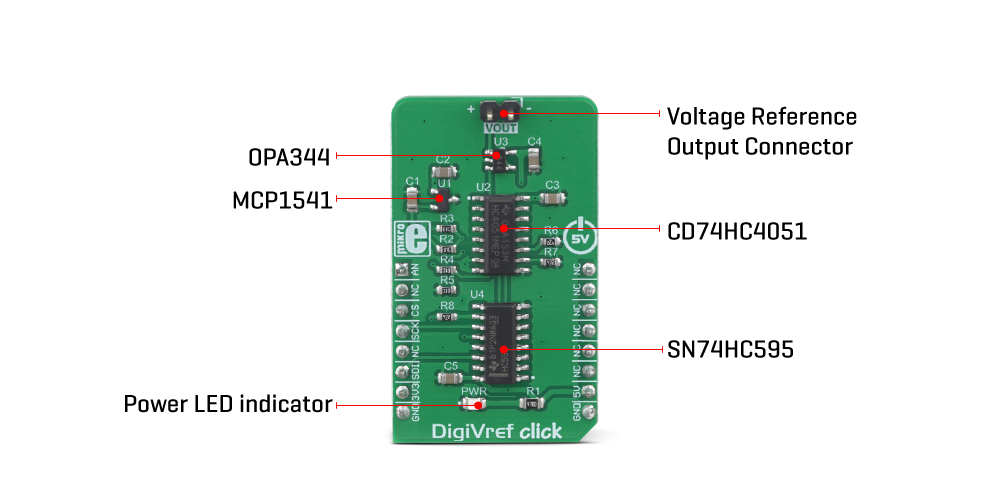
The voltage reference output of 4.096V (VREF) is routed to a common pin of the CD74HC4051, an analog multiplexer/demultiplexer IC, by Texas Instruments. This circuit has a one-to-eight internal switch with a digitally selected position. The position of the switch can be selected by applying logic levels to pins S0 to S2. Four outputs of the CD74HC4051 are routed to a voltage divider circuit composed of four 10K resistors. By routing the VREF across the voltage divider, one of four output voltage reference values can be selected, depending on the selected switch position. The output voltage (VOUT) can be set to one of the following values: 1.024V, 2.048V, 3.072V, and 4.096V.
The CD74HC4051 is controlled by the SN74HC595, an 8-bit shift register IC with tri-state output registers, by Texas Instruments. The SN74HC595 allows the data to be shifted in and then latched at the output. The state of the output pins will not change, as long as there is no new data shifted in and latched to the parallel output register (or as long as the #OE pin stays LOW, but it is hardwired to the GND on this Click board™). This allows the Click board™ to be completely independent on the SPI interface, even if it is disconnected at some point. Once set, the selected reference voltage will be available at the VOUT connector (standard 1x2-pin header with 2.54mm pitch), as long as the Click board™ is powered.
There are two control pins available on the CD74HC4051 since there are only 4 valid positions. Control pin S2 is grounded, so the CD74HC4051 is controlled by means of two pins: S0 and S1. These pins are routed to Q1 and Q2 outputs of the SN74HC595 IC. The SN74HC595 IC is controlled over the SPI interface, with its pins routed to the respective mikroBUS™ pins (CS, MOSI, SCK). Note that SPI data values that set pins other than Q1 and Q2, will not have any effect on this Click board™.
Besides the VOUT connector, the VOUT voltage is also routed to the AN pin of the mikroBUS™, allowing it to be used by the host MCU. Therefore, a note should be taken that the Click board™ is not intended to be used with 3.3V MCUs, especially if they do not have 5V tolerant pins. To use the Click board™ with 3.3V MCUs, a proper level shifting circuit must be used.
Specifications
| Type | Measurements |
| Applications | It is a perfect solution to be used in various A/D conversion applications, measurement applications, logic voltage comparators, precise power supply applications, and other applications that require switchable and regulated voltage reference. |
| On-board modules | MCP1541, a precise voltage reference IC by Microchip; CD74HC4051, an analog multiplexer and demultiplexer IC, SN74HC595, an 8-bit shift register IC with tri-state output registers, both by Texas Instruments. |
| Key Features | Very stable buffered selectable voltage reference, digital selection over the SPI interface thanks to the latch ability of the SR IC, it does not require the SPI interface to be connected once the output voltage is selected, and more. |
| Interface | Analog,SPI |
| Input Voltage | 5V |
| Click board size | M (42.9 x 25.4 mm) |
Pinout diagram
This table shows how the pinout on DigiVref Click corresponds to the pinout on the mikroBUS™ socket (the latter shown in the two middle columns).
| Notes | Pin | Pin | Notes | ||||
|---|---|---|---|---|---|---|---|
| NC | 1 | AN | PWM | 16 | NC | ||
| NC | 2 | RST | INT | 15 | NC | ||
| SPI Chip Select | CS | 3 | CS | RX | 14 | NC | |
| SPI Clock | SCK | 4 | SCK | TX | 13 | NC | |
| NC | 5 | MISO | SCL | 12 | NC | ||
| SPI Data IN | SDI | 6 | MOSI | SDA | 11 | NC | |
| NC | 7 | 3.3V | 5V | 10 | 5V | Power Supply | |
| Ground | GND | 8 | GND | GND | 9 | GND | Ground |
Onboard settings and indicators
| Label | Name | Default | Description |
|---|---|---|---|
| PWR | PWR | - | Power LED indicator |
| J1 | VOUT | - | Voltage reference output connector |
DigiVref Click electrical specifications
| Description | Min | Typ | Max | Unit |
|---|---|---|---|---|
| Voltage at the VOUT connector | 1.024 | - | 4.096 | V |
Software support
We provide a library for the DigiVref Click on our LibStock page, as well as a demo application (example), developed using MikroElektronika compilers. The demo can run on all the main MikroElektronika development boards.
Library Description
The library contains a function for setting a reference output voltage which can be 1030mV, 2046mv, 3070mV or 4096mV.
Key functions:
void digivref_setOutputVoltage( uint8_t Vref )- Function for set reference output voltage
Examples description
The application is composed of the three sections :
- System Initialization - Initializes SPI driver and sets CS pin as OUTPUT.
- Application Initialization - Initialization driver init.
- Application Task - (code snippet) - Changes the reference output voltage every 3 seconds.
void applicationTask()
{
    digivref_setOutputVoltage( _DIGIVREF_REF_VOLTAGE_4096mV );
    Delay_ms( 3000 );
    digivref_setOutputVoltage( _DIGIVREF_REF_VOLTAGE_3070mV );
    Delay_ms( 3000 );
    digivref_setOutputVoltage( _DIGIVREF_REF_VOLTAGE_2046mV );
    Delay_ms( 3000 );
    digivref_setOutputVoltage( _DIGIVREF_REF_VOLTAGE_1030mV );
    Delay_ms( 3000 );
    digivref_setOutputVoltage( _DIGIVREF_REF_VOLTAGE_2046mV );
    Delay_ms( 3000 );
    digivref_setOutputVoltage( _DIGIVREF_REF_VOLTAGE_3070mV );
    Delay_ms( 3000 );
}

The full application code, and ready to use projects can be found on our LibStock page.
Other mikroE Libraries used in the example:
SPI
Additional notes and information
Depending on the development board you are using, you may need USB UART click, USB UART 2 click or RS232 click to connect to your PC, for development systems with no UART to USB interface available on the board. The terminal available in all MikroElektronika compilers, or any other terminal application of your choice, can be used to read the message.
Downloads
mikroBUS™ Standard specificationWrite a review
Your Name:
Your Review:
Note: HTML is not translated!
Rating:
Bad
Good
Enter the code in the box below:
-
 ₹3,049.00


© 2024, MG Automation Technologies. Powered by MG Super LABS.Find us on Google+
Designed with by Ish Gupta