ATA6563 click
Product Code: MIKROE-2334


ATA6563 features
The ATA6563 is a high-speed CAN transceiver that provides an interface between a controller area network (CAN) protocol controller and the physical two-wire CAN bus.
The transceiver is designed for high-speed (up to 5 Mbps) CAN applications in the automotive industry, providing differential transmit and receive capability to (a microcontroller with) a CAN protocol controller. It offers improved electromagnetic compatibility (EMC) and electrostatic discharge (ESD) performance.
The transceiver is CAN FD (Flexible data-rate) ready, meaning it has increased data rates in comparison with classic CAN.
How the click works
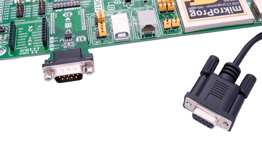
ATA6563 click is connected to a CAN bus via the DB9 cable, which then communicates with the network.
Specifications
| Type | CAN |
| Applications | Classical CAN and CAN FD networks in Automotive, Industrial, Aerospace, Medical and Consumer applications. |
| On-board modules | ATA6563 high-speed CAN transceiver from Microchip |
| Key Features | Optimized for CAN FD at 2 and 5 Mbps operation, maximum propagation delay: 210ns; the chip supports CAN 2.0 and CAN with flexible data rates. |
| Interface | UART |
| Input Voltage | 3.3V or 5V |
| Click board size | L (57.15 x 25.4 mm) |
Pinout diagram
This table shows how the pinout on ATA6563 click corresponds to the pinout on the mikroBUS™ socket (the latter shown in the two middle columns).
| Notes | Pin | Pin | Notes | ||||
|---|---|---|---|---|---|---|---|
| Standby select | STBY | 1 | AN | PWM | 16 | NC | |
| NC | 2 | RST | INT | 15 | NC | ||
| NC | 3 | CS | TX | 14 | RX | UART data receive | |
| NC | 4 | SCK | RX | 13 | TX | UART data transmit | |
| NC | 5 | MISO | SCL | 12 | NC | ||
| NC | 6 | MOSI | SDA | 11 | NC | ||
| Power supply | +3.3V | 7 | 3.3V | 5V | 10 | +5V | Power supply |
| Ground | GND | 8 | GND | GND | 9 | GND | Ground |
Jumpers and settings
| Designator | Name | Default Position | Default Option | Description |
|---|---|---|---|---|
| JP1 | VIO SEL | Left | 3V3 | VIO Supply Voltage Selection 3V3/5V, left position 3V3, right position 5V |
| JP2 | MODE SEL | Left | ON | Selection of the standby feature; default is always on, right option switches to the STB pin on the mikroBUS™ |
Additional pins
| Name | I/O | Description |
|---|---|---|
| CANL | I/O | CAN lines, same as on DB9 connector |
| CANH | I/O | CAN lines, same as on DB9 connector |
| TXD | I | UART lines, same as on the mikroBUS™ |
| RXD | O | UART lines, same as on the mikroBUS™ |
Programming
Code examples for ATA6563 click, written for MikroElektronika hardware and compilers are available on Libstock.
Code snippet
A simple example of the ATA6563 library usage. The example waits until 8 bytes are received on the RX and then prints the received data using the other UART module.
01 void main()
02 {
03     int i = 0;
04     system_init();
05     while( 1 ) {
06         if( Button( &GPIOA_IDR , 5, 100, 1 ) ){
07             ata6563_send( TX_DATA, sizeof( TX_DATA ) );
08             TFT_Write_Text( "Data Sent", 50, 100 );
09         }
10         if( ( chk = ata6563_rdy() ) == 8 ){
11             ata6563_read( buf, chk );
12             for( i = 0; i < chk; i++ )
13                  UART1_Write( buf[ i ] );
14         }
15     }
16 }
Downloads
mikroBUS™ Standard specificationATA6563 datasheet
ATA6563 click schematic
LibStock: ATA6563 click library
Write a review
Your Name:
Your Review:
Note: HTML is not translated!
Rating:
Bad
Good
Enter the code in the box below:
-
 ₹2,209.00


© 2024, MG Automation Technologies. Powered by MG Super LABS.Find us on Google+
Designed with by Ish Gupta