Pololu G2 High-Power Motor Driver 24v13
Product Code: Pololu #2992


e operation). With PWM high, the motor outputs will be driven according to the DIR input. This allows two modes of operation: sign-magnitude, in which the PWM duty cycle controls the speed of the motor and DIR controls the direction, and locked-antiphase, in which a pulse-width-modulated signal is applied to the DIR pin with PWM held high.
In locked-antiphase operation, a low duty cycle drives the motor in one direction, and a high duty cycle drives the motor in the other direction; a 50% duty cycle turns the motor off. A successful locked-antiphase implementation depends on the motor inductance and switching frequency smoothing out the current (e.g. making the current zero in the 50% duty cycle case), so a high PWM frequency might be required.
| Motor Driver Truth Table | ||||
|---|---|---|---|---|
| PWM | DIR | OUTA | OUTB | Operation |
| H | H | H | L | Forward |
| H | L | L | H | Reverse |
| L | X | L | L | Brake |
PWM frequency
The motor driver supports PWM frequencies as high as 100 kHz, but note that switching losses in the driver will be proportional to the PWM frequency. Typically, around 20 kHz is a good choice for sign-magnitude operation since it is high enough to be ultrasonic, which results in quieter operation.
A pulse on the PWM pin must be high for a minimum duration of approximately 0.5 us before the outputs turn on for the corresponding duration (any shorter input pulse does not produce a change on the outputs), so low duty cycles become unavailable at high frequencies. For example, at 100 kHz, the pulse period is 10 us, and the minimum non-zero duty cycle achievable is 0.5/10, or 5%.
Current sensing and limiting
The driver’s current sense pin, CS, outputs a voltage proportional to the motor current while the H-bridge is driving. The output voltage is about 40 mV/A plus a small offset, which is typically about 50 mV.
The CS output is only active while the H-bridge is in drive mode; it is inactive (low) when the driver is in brake mode (slow decay), which happens when the PWM input is low or when current limiting is active. Current will continue to circulate through the motor when the driver begins braking, but the voltage on the CS pin will not accurately reflect the motor current in brake mode. The CS voltage is used internally by the motor driver, so to avoid interfering with the driver’s operation, you should not add a capacitor to this pin or connect a load that draws more than a few mA from it.
The G2 driver has the ability to limit the motor current through current chopping: once the motor drive current reaches a set threshold, the driver goes into brake mode (slow decay) for a brief time before applying power to drive the motor again. This makes it more practical to use the driver with a motor that might only draw a few amps while running but can draw many times that amount (tens of amps) when starting.
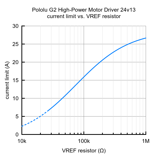
The current limiting threshold is set to about 30 A by default. You can lower the limit by connecting an additional resistor between the VREF pin and the adjacent GND pin; the graph below shows how the current limit relates to the VREF resistor value. For example, adding a 100 kΩ resistor between VREF and GND lowers the current limit to approximately 16 A. Note that the current limiting is less accurate at especially low settings (indicated by the dashed portion of the curve).
 |
Fault conditions
The motor driver can detect several fault states that it reports by driving the FLT pin low; this is an open-drain output that should be pulled up to your system’s logic voltage. The detectable faults include short circuits on the outputs, under-voltage, and over-temperature. All of the faults disable the motor outputs but are not latched, meaning the driver will attempt to resume operation when the fault condition is removed (or after a delay of a few milliseconds in the case of the short circuit fault). The over-temperature fault provides a weak indication of the board being too hot, but it does not directly indicate the temperature of the MOSFETs, which are usually the first components to overheat, so you should not count on this fault to prevent damage from over-temperature conditions.
Real-world power dissipation considerations
The motor driver can handle large current spikes for short durations (e.g. 100 A for a few milliseconds). The peak ratings are for quick transients (e.g. when a motor is first turned on), and the continuous rating of 13 A is dependent on various conditions, such as the ambient temperature. The actual current you can deliver will depend on how well you can keep the motor driver cool. The driver’s printed circuit board is designed to draw heat out of the MOSFETs, but performance can be improved by adding a heat sink.
Warning: This motor driver has no over-temperature shut-off. An over-temperature or over-current condition can causepermanent damage to the motor driver. You might consider using either the driver’s integrated current sense output or anexternal current sensor to monitor your current draw.
Included hardware
|
|
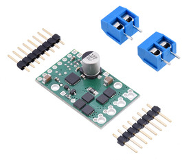

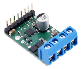
Two 8-pin straight breakaway male headers and two 2-pin 5mm terminal blocks are included with each motor driver. You can solder the terminal blocks to the four large through-holes to make your motor and motor power connections, or you can solder one of the 1×8 0.1″ header strips into the smaller through-holes that border these larger holes. Note, however, that the terminal blocks are only rated for 16 A, and each header pin pair is only rated for a combined 6 A, so for higher-power applications, thick wires should be soldered directly to the board.
The other 1×8 header strip can be soldered into the small holes on the logic connection side of the board to enable use with solderless breadboards, perfboards, or 0.1″ connectors, or you can solder wires directly to these holes for the most compact installation.
Note: In most applications, it is necessary to connect an additional large capacitor (not included) across the power supply, as described under “Connections” above.
The board has two 0.086″ (2.18 mm) diameter mounting holes intended for #2 or M2 screws (not included); they are separated by 0.62″ (15.75 mm) both horizontally and vertically.
Differences from original high-power motor drivers
The G2 high-power motor driver is designed to work as a near drop-in replacement for our original high-power motor drivers; this version, the 24v13, is comparable to the original 24v12 but can provide slightly higher output currents in most situations. The overall board dimensions and locations of the mounting holes and all required pins are the same for both versions.
This second-generation driver adds new features including reverse-voltage protection on the power supply inputs and basic current sensing and current limiting functionality. It also works with lower logic voltages, making it compatible with 3.3 V systems; however, note that it has a slightly higher minimum motor supply voltage than the original HPMD (6.5 V vs. 5.5 V).
The pinout of the G2 driver differs from the original in several ways:
- The SLP pin must be connected to logic high to enable the G2 driver. (The corresponding RESET pin on the original driver could be left disconnected if unused.)
- The G2 driver has only one fault pin, which is an open-drain output that is driven low when a fault occurs. (The original driver had two fault pins that were driven high to indicate faults.)
- A current sense output is available on the G2 driver in place of the second fault pin.
- A new VREF pin and adjacent GND pin let you connect a resistor to adjust the G2 driver’s current limit.
- The G2 driver provides a 3.3 V output instead of the original driver’s 5 V output.
G2 high-power motor driver versions
There are currently two versions of the G2 high-power motor driver, both with the same pinout. The following table provides a comparison of the G2 drivers:
| Pololu G2 High-Power Motor Drivers | |||
|---|---|---|---|
| Name | Absolute max input voltage |
Max nominal battery voltage |
Max continuous current |
| G2 High-Power Motor Driver 18v17 | 30 V | 18 V | 17 A |
| G2 High-Power Motor Driver 24v13 | 40 V | 28 V | 13 A |
Note: As an alternative to these motor drivers, our Simple Motor Controllers have similar power characteristics and offer high-level interfaces (e.g. USB, RC hobby servo pulses, analog voltages, and TTL serial commands) that make them easier to use for some applications.
Write a review
Your Name:
Your Review:
Note: HTML is not translated!
Rating:
Bad
Good
Enter the code in the box below:
-
 ₹3,999.00
© 2024, MG Automation Technologies. Powered by MG Super LABS.Find us on Google+
Designed with by Ish Gupta