3-Channel Wide FOV Time-of-Flight Distance Sensor Using OPT3101 (No Headers)
")
")
")
")
")

Overview
This board is a 3-channel time-of-flight proximity and distance sensor module based on the OPT3101 IC from Texas Instruments. Unlike conventional IR sensors that use the intensity of reflected light to estimate the distance to an object, this board emits 940 nm infrared light pulsed at 10 MHz, and then measures the phase (delay) of the reflected signal, which corresponds to the distance to the target object. It also measures the amplitude of the signal, which indicates how bright/reflective/close the object is.
This board has three channels that each cover approximately 50° to 60°, giving the sensor a wide field of view (FOV). In favorable conditions, the sensor can measure objects at distances up to 1 m. Distance measurements are available through the sensor’s I²C interface, which is also used to configure the sensor.
Specifications
- Dimensions: 1.1″ × 1.2″ (27.9 mm × 30.5 mm)
- Weight without header pins: 2.7 g (0.095 oz)
- Operating voltage: 2.5 V to 5.5 V
- Sensor channels: 3 (each with an FOV of approximately 50° – 60° for a combined FOV of nearly 180°)
- Supply current: 130 mA (typical average during operation in high-brightness mode with 3.3 V power supply)
- Distance measuring range: up to 1 m (3.3 ft) (depends on the target object; see the FAQs tab for more information on distance measurement accuracy)
Connections
Four connections are necessary to use the OPT3101 board: GND, VIN, SDA, and SCL. The VIN pin should be connected to a 2.5 V to 5.5 V source, and GND should be connected to 0 volts. The board’s I²C pins (SCL and SDA) should be connected to an I²C bus operating at the same logic level as VIN.
Pinout
| Pin | Description |
|---|---|
| GND | The ground (0 V) connection for your power supply. Your I²C control source must also share a common ground with this board. |
| VIN | This is the main 2.5 V to 5.5 V power supply connection. |
| SDA | Level-shifted I²C data line: high is VIN, low is 0 V. Pulled up to VIN with a 10kΩ pull-up resistor. |
| SCL | Level-shifted I²C clock line: high is VIN, low is 0 V. Pulled up to VIN with a 10kΩ pull-up resistor. |
| GP1 | Configurable 3.3 V I/O pin. This pin is not level-shifted. |
| GP2 | Configurable 3.3 V I/O pin. This pin is not level-shifted. |
| RST/MS | Input pin that can be used to reset the board or trigger a new sample. (Both of those functions can also be done with I²C.) Pulled up to 3.3 V with a 10kΩ pull-up resistor. This pin is not level-shifted. |
Schematic diagram
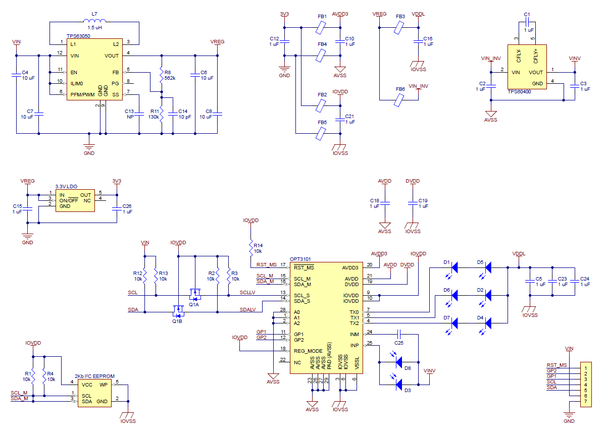 |
This schematic is also available as a downloadable PDF (144k pdf).
I²C communication
The OPT3101 can be configured, controlled, and queried through the I²C bus. Level shifters on the I²C clock (SCL) and data (SDA) lines enable I²C communication with microcontrollers operating at the same voltage as VIN. A detailed explanation of the I²C interface on the OPT3101 can be found in the “I2C slave” section of the OPT3101 datasheet, and more detailed information about I²C in general can be found in NXP’s I²C-bus specification (1MB pdf). The sensor’s 7-bit slave address is 0x58 (1011000 in binary).
Calibration
Each board includes a 256-byte EEPROM that holds an individualized factory calibration. The OPT3101 automatically loads the calibration when it starts up. This calibration defines a distance reading of 100 mm to correspond to an object that is 100 mm from the edge of the board.
We recommend not doing the internal crosstalk calibration procedure described in TI’s documentation; the effect it would have has already been incorporated into the illumination crosstalk numbers in the factory calibration.
Configuration
The main configuration options that you can choose for the OPT3101 are the channel, brightness, and sample rate. These options are set over I²C, and you can change them between samples.
The channel setting determines which pair of IR LEDs will turn on, and thus determines the direction in which the sensor will be most sensitive to objects. There are three channels: TX0 (left), TX1 (middle), and TX2 (right).
There are two brightness settings available for the IR LEDs: low and high (also known as HDR0 and HDR1, respectively). Low brightness mode only works well for nearby objects (within about 20 cm). High brightness mode works for longer ranges, but objects that are too reflective or too close can cause the sensor to saturate, meaning that it fails to measure a distance. You can configure the OPT3101 to use one of these brightnesses, or you can make it use an adaptive brightness mode, where it automatically selects between low or high brightness.
The measurements performed by the OPT3101 are divided into basic units called a frame or a sample. Each frame has a specific configuration, but you can change the configuration between frames. You can configure the OPT3101 to start frames continuously, or to wait for your signal before starting a frame (which is called monoshot mode). When a frame is complete, you can read its results from the OPT3101’s output registers.
Dimensions
| Size: | 1.1″ × 1.2″ |
|---|---|
| Weight: | 2.4 g |
General specifications
| Maximum range: | 1 m1 |
|---|---|
| Channels: | 3 |
| Interface: | I²C |
| Minimum operating voltage: | 2.5 V |
| Maximum operating voltage: | 5.5 V |
| Supply current: | 130 mA2 |
| Header pins soldered?: | N |
Identifying markings
| PCB dev codes: | irs15j |
|---|---|
| Other markings: | 0J12947 |
Notes:
- Effective range depends on several factors including target size and reflectivity.
- Typical average during operation in high-brightness mode with 3.3 V power supply.
Enter the code in the box below: