30:1 Metal Gearmotor 37Dx52L mm with 64 CPR Encoder
Product Code: Pololu #1443


Overview
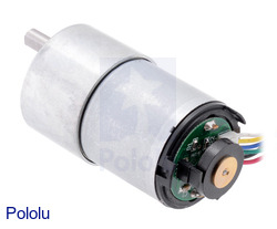
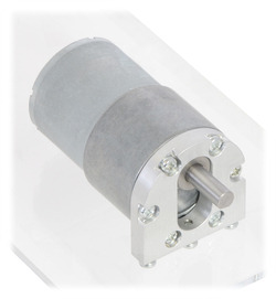
Discontinuation notice: These gearmotors have been replaced by functionally identical versions with plastic end caps over the encoders (they use the same motor, encoder, and gearboxes). The protective end caps on the new versions can be easily removed to give them nearly the same dimensions as the older versions without end caps, but there is a little bit of base plastic that will remain as shown in the right picture below.
|
|
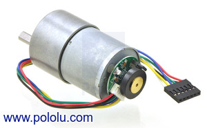
This powerful brushed DC gearmotor is available in six different gear ratios and features an integrated quadrature encoder with 64 counts per revolution (CPR) of the motor shaft. The motor and encoder portion is available by itself (no gearbox), and versions without the encoder are also available.
| Gear Ratio | No-Load Speed @ 12 V |
Stall Torque @ 12 V |
Stall Current @ 12 V |
 With Encoder |
 Without Encoder |
|---|---|---|---|---|---|
| 1:1 | 11,000 RPM | 5 oz-in | 5 A | motor without gearbox | |
| 19:1 | 500 RPM | 84 oz-in | 5 A | 37Dx52L mm | 37Dx52L mm |
| 30:1 | 350 RPM | 110 oz-in | 5 A | 37Dx52L mm | 37Dx52L mm |
| 50:1 | 200 RPM | 170 oz-in | 5 A | 37Dx54L mm | 37Dx54L mm |
| 70:1 | 150 RPM | 200 oz-in | 5 A | 37Dx54L mm | 37Dx54L mm |
| 100:1 | 100 RPM | 220 oz-in | 5 A | 37Dx57L mm | 37Dx57L mm |
| 131:1 | 80 RPM | 250 oz-in | 5 A | 37Dx57L mm | 37Dx57L mm |
Note: Stalling or overloading gearmotors can greatly decrease their lifetimes and even result in immediate damage. Stalls can also result in rapid (potentially on the order of seconds) thermal damage to the motor windings and brushes; a general recommendation for brushed DC motor operation is 25% or less of the stall current.
These motors are intended for use at 12 V, though in general, these kinds of motors can run at voltages above and below the nominal voltage (they can begin rotating at voltages as low as 1 V). Lower voltages might not be practical, and higher voltages could start negatively affecting the life of the motor.
Details for item #1443
Exact gear ratio: ``(25×30×40) / (10×10×10) = bb(30:1)``
April 2014 update: We have changed the gear ratio in this product’s name from “29:1” to “30:1” so the name more accurately reflects the product. The product itself has not changed.
Gearmotor accessories
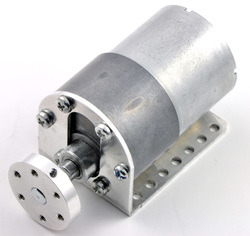
The face plate has six mounting holes evenly spaced around the outer edge threaded for M3 screws. These mounting holes form a regular hexagon and the centers of neighboring holes are 15.5 mm apart. We carry two brackets for these gearmotors: a stamped aluminum L-bracket (sold in pairs) and a sturdier, tombstone-style machined aluminum bracket (sold individually):
|
|
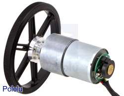
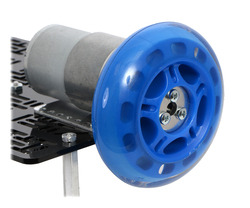
The 6 mm diameter gearbox output shaft works with the Pololu universal aluminum mounting hub for 6mm shafts, which can be used to mount our larger Pololu wheels (80mm- and 90mm-diameter) or custom wheels and mechanisms to the gearmotor’s output shaft as shown in the left picture below. Alternatively, you could use our 6mm scooter wheel adapter to mount many common scooter, skateboard, and inline skate wheels to the gearmotor’s output shaft as shown in the right picture below:
|
|
Finally, our 12mm hex wheel adapter for 6mm shaft (also available in an extended version) lets you use these motors with many common hobby RC wheels, including Dagu Wild Thumper Wheels:
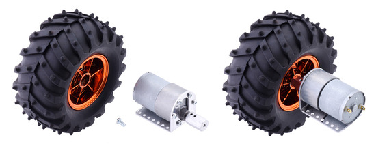  |
| 12mm Hex Wheel Adapter for 6mm Shaft connecting a Wild Thumper Wheel to a 37D mm Metal Gearmotor. |
|---|
Dimensions
The diagram below shows the dimensions (in mm) of the 37D mm line of gearmotors. The value of X is 22 mm for the 19:1 37Dx52L mmand 30:1 37Dx52L mm versions, 24 mm for the 50:1 37Dx54L mm and 70:1 37Dx54L mm versions, and 26.5 mm for the 100:1 37Dx57L mm and 131:1 37Dx57L mm versions. Note that the encoder PCB and magnetic disc are not shown in this dimension diagram. The encoder assembly extends an additional 12.5 mm beyond the rear of the motor.
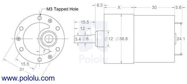 |
| 37D mm metal gearmotor dimensions (units in mm). |
|---|
Warning: Do not screw too far into the mounting holes as the screws can hit the gears. We recommend screwing no further than 3mm (1/8") into the screw hole.
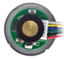 |
| 37D mm metal gearmotor with 64 CPR encoder (no end cap). |
|---|
Using the Encoder
A two-channel Hall effect encoder is used to sense the rotation of a magnetic disk on a rear protrusion of the motor shaft. The quadrature encoder provides a resolution of 64 counts per revolution of the motor shaft when counting both edges of both channels. To compute the counts per revolution of the gearbox output, multiply the gear ratio by 64. The motor/encoder has six color-coded, 11" (28 cm) leads terminated by a 1×6 female header with a 0.1″ pitch, as shown in the main product picture. This header works with standard 0.1″ male headers and our malejumper and precrimped wires. If this header is not convenient for your application, you can pull the crimped wires out of the header or cut the header off. The following table describes the wire functions:
| Color | Function |
|---|---|
| Red | motor power (connects to one motor terminal) |
| Black | motor power (connects to the other motor terminal) |
| Green | encoder GND |
| Blue | encoder Vcc (3.5 – 20 V) |
| Yellow | encoder A output |
| White | encoder B output |
The Hall sensor requires an input voltage, Vcc, between 3.5 and 20 V and draws a maximum of 10 mA. The A and B outputs are square waves from 0 V to Vcc approximately 90° out of phase. The frequency of the transitions tells you the speed of the motor, and the order of the transitions tells you the direction. The following oscilloscope capture shows the A and B (yellow and white) encoder outputs using a motor voltage of 12 V and a Hall sensor Vcc of 5 V:
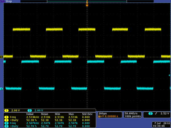 |
| Encoder A and B outputs for 37D mm metal gearmotor with 64 CPR encoder (motor running at 12 V). |
|---|
By counting both the rising and falling edges of both the A and B outputs, it is possible to get 64 counts per revolution of the motor shaft. Using just a single edge of one channel results in 16 counts per revolution of the motor shaft, so the frequency of the A output in the above oscilloscope capture is 16 times the motor rotation frequency.
Selecting the Right Gearmotor
We offer a wide selection of metal gearmotors that offer different combinations of speed and torque. Our metal gearmotor comparison table can help you find the motor that best meets your project’s requirements.
 |
Write a review
Your Name:
Your Review:
Note: HTML is not translated!
Rating:
Bad
Good
Enter the code in the box below:
-
 ₹2,399.00


© 2025, MG Automation Technologies. Powered by MG Super LABS.Find us on Google+
Designed with by Ish Gupta