6DOF IMU 4 Click
Product Code: MIKROE-3410


Features such as low power consumption, high precision of motion detection, high shock tolerance up to 20,000 g, a programmable full-scale range for increased accuracy, allow 6DOF IMU 4 click to be used for development of different types of motion detection and MotionTracking™ applications: motion-based game controllers, 3D and gesture controllers, IoT applications, wearable motion sensing applications, and similar applications.
How does it work?
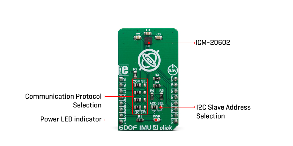
6DOF IMU 4 click is based on the ICM-20602, a high-performance, 6-axis MEMS MotionTracking™ IC from TDK Invensense. It is an advanced, integrated microelectromechanical gyroscope and accelerometer sensor (MEMS). The ICM-20602 is produced using the patented CMOS-MEMS fabrication platform, specialized in MEMS production and its integration with accompanying logic sections, on a wafer level. This allows very high integration and very small dimensions, at an affordable cost. The IC contains a separate accelerometer and gyroscope MEMS on each axis. The output of each MEMS is processed and digitized by a separate sigma-delta 16-bit A/D converter (ADC).
Three-axis gyroscope MEMS can be programmed to measure the rotation about each axis, in four different ranges of rotational speed (degrees per angle, DPS): ±250, ±500, ±1000, and ±2000. Three-axis accelerometer MEMS can be programmed to measure the acceleration along each axis, in four different acceleration ranges: ±2g, ±4g, ±8g, and ±16g. The user can select an optimal range for both properties, depending on the application requirements.
The ICM-20602 incorporates a powerful programmable interrupt engine. The interrupt engine can generate a signal on the interrupt pin for several interrupt sources, including FIFO Buffer overflow, Data Ready, I2C Master Error, and I2C Slave Error. The interrupt is routed to the INT pin of the mikroBUS™.
A FIFO buffer helps to further reduce the processing load, offering temporary storage for the output data. The MPU6050 features a FIFO buffer with the capacity of 1024 bytes. The user can select which data will be stored in the FIFO buffer: gyro data, accel data, temperature readings, and auxiliary sensor readings. Once the FIFO buffer is full, it will start discarding the oldest data, allowing new data to be written. The FIFO buffer overflow condition can be used to trigger an interrupt, alerting the host MCU about its status.
Synchronization with an external digital signal is possible over the FSYNC pin. This pin is routed to the PWM pin of the mikroBUS™, labeled as SYN. The ICM-20602 can be programmed to trigger an interrupt on the FSYN pin activity. The polarity of the signal pulse applied at the FSYN pin can also be programmed.
6DOF IMU 4 click supports both SPI and I2C communication interfaces, allowing it to be used with a wide range of different MCUs. The communication interface can be chosen by moving SMD jumpers grouped under the COM SEL to an appropriate position (SPI or I2C). The slave I2C address can also be configured by a SMD jumper, when the Click board™ is operated in the I2C mode: a SMD jumper labeled as ADD SEL is used to set the least significant bit (LSB) of the I2C address. When set to 1, the 7-bit I2C slave address becomes 0b1101000x. If set to 0, the address becomes 0b1101001x. The last digit (x) is the R/W bit.
This Click Board™ uses both I2C and SPI communication interfaces. It is designed to be operated only with 3.3V logic levels. A proper logic voltage level conversion should be performed before the Click board™ is used with MCUs with logic levels of 5V.
Specifications
| Type | Motion |
| Applications | It is a perfect solution for development of different types of motion detection and MotionTracking™ applications: motion-based game controllers, 3D and gesture controllers, IoT applications, wearable motion sensing applications, and similar applications. |
| On-board modules | ICM-20602, a high-performance, 6-axis MEMS MotionTracking™ IC from TDK Invensense. |
| Key Features | Six independent MEMS (one on each axis), sampled by a dedicated 16-bit ADC, external synchronization pin, output data filtering, selectable accel and gyro ranges for increased precision, a FIFO buffer with 1kb of memory, etc. |
| Interface | I2C,SPI |
| Input Voltage | 3.3V |
| Click board size | M (42.9 x 25.4 mm) |
Pinout Diagram
This table shows how the pinout on 6DOF IMU 4 Click corresponds to the pinout on the mikroBUS™ socket (the latter shown in the two middle columns).
| Notes | Pin | Pin | Notes | ||||
|---|---|---|---|---|---|---|---|
| NC | 1 | AN | PWM | 16 | SYN | External Sync | |
| NC | 2 | RST | INT | 15 | INT | Interrupt | |
| SPI Chip Select | CS | 3 | CS | RX | 14 | NC | |
| SPI Clock | SCK | 4 | SCK | TX | 13 | NC | |
| SPI Data OUT | SDO | 5 | MISO | SCL | 12 | SCL | I2C Clock |
| SPI Data IN | SDI | 6 | MOSI | SDA | 11 | SDA | I2C Data |
| Power Supply | 3.3V | 7 | 3.3V | 5V | 10 | NC | |
| Ground | GND | 8 | GND | GND | 9 | GND | Ground |
Onboard Settings And Indicators
| Label | Name | Default | Description |
|---|---|---|---|
| LD1 | PWR | - | Power LED indicator |
| JP1, JP4 | COM SEL | Left | Communication interface selection: left position I2C, right position SPI |
| JP5 | ADDR SEL | Left | Slave I2C address LSB selection: left position 0, right position 1 |
Software Support
We provide a library for the 6DOF IMU 4 Click on our LibStock page, as well as a demo application (example), developed using MikroElektronika compilers. The demo can run on all the main MikroElektronika development boards.
Library Description
The library performs a gyroscope, accelerometer and temperature measurements and control of the 6DOF IMU 4 Click board. User also can select a desired full scale range, offset and threshold for the desired measurement. The control of the 6DOF IMU 4 Click board can be performed by using I2C or SPI interface. For more details check documentation.
Key functions:
T_C6DOFIMU4_RETVAL c6dofimu4_writeByte( uint8_t regAddr, uint8_t dataIn )- Function writes one byte data to the desired register.T_C6DOFIMU4_RETVAL c6dofimu4_readBytes( uint8_t startAddr, uint8_t *dataOut, uint8_t nBytes )- Function performs a sequential data reading starting from the desired address.void c6dofimu4_getData( T_c6dofimu4_axis *accelOut, T_c6dofimu4_axis *gyroOut, int8_t *tempOut )- Function performs a data reading and all necessary calculations to get accelerometer, gyroscope and temperature data.T_C6DOFIMU4_RETVAL c6dofimu4_setFSR( uint8_t gyro_resol, uint8_t accel_resol )- Function selects a measurement full scale range.
Examples description
The application is composed of the three sections :
- System Initialization - Initializes peripherals and pins.
- Application Initialization - Initializes I2C or SPI interface and performs a device reset and configurations.
- Application Task - (code snippet) - Waits until data is ready and then reads the all data registers, accelerometer, gyroscope and temperature data, and shows results to the uart terminal every 500ms.
void applicationTask()
{
    dataReady = c6dofimu4_getStatus( _C6DOFIMU4_DATA_RDY_INT_MASK );
    while (dataReady != _C6DOFIMU4_DATA_RDY_INT_OCCURED)
    {
        dataReady = c6dofimu4_getStatus( _C6DOFIMU4_DATA_RDY_INT_MASK );
    }

    c6dofimu4_getData( &accel_data, &gyro_data, &temperature );

    mikrobus_logWrite( "** Accelerometer values :", _LOG_LINE );
    logAxis( &accel_data, &accelUnit[0] );
    mikrobus_logWrite( "", _LOG_LINE );

    mikrobus_logWrite( "** Gyroscope values :", _LOG_LINE );
    logAxis( &gyro_data, &gyroUnit[0] );
    mikrobus_logWrite( "", _LOG_LINE );

    mikrobus_logWrite( "** Temperature value : ", _LOG_TEXT );
    ShortToStr( temperature, text );
    mikrobus_logWrite( text, _LOG_TEXT );
    mikrobus_logWrite( tempUnit, _LOG_LINE );
    mikrobus_logWrite( "-------------------------------------------------", _LOG_LINE );
    mikrobus_logWrite( "", _LOG_LINE );

    Delay_ms( 500 );
}
Additional Functions :
- floatCut - Makes to float values be rounded on two decimal places.
- logAxis - Logs axis values for the desired measured data on the uart terminal.
The full application code, and ready to use projects can be found on our LibStock page.
Other mikroE Libraries used in the example:
I2CSPIUART
Additional notes and informations
Depending on the development board you are using, you may need USB UART click, USB UART 2 click or RS232 click to connect to your PC, for development systems with no UART to USB interface available on the board. The terminal available in all MikroElektronika compilers, or any other terminal application of your choice, can be used to read the message.
MIKROSDK
This click board is supported with mikroSDK - MikroElektronika Software Development Kit. To ensure proper operation of mikroSDK compliant click board demo applications, mikroSDK should be downloaded from the LibStock and installed for the compiler you are using.
For more information about mikroSDK, visit the official page.
Downloads
mikroBUS™ Standard specification
Write a review
Your Name:
Your Review:
Note: HTML is not translated!
Rating:
Bad
Good
Enter the code in the box below:
-
 ₹1,359.00


© 2026, MG Automation Technologies. Powered by MG Super LABS.Find us on Google+
Designed with by Ish Gupta