6DOF IMU 8 click
Product Code: MIKROE-3447


The ISM330DLC is produced using well-proven microelectromechanical sensor (MEMS) manufacturing processes, along with the CMOS technologies that allow a high integration scale on a wafer level, providing good component matching and improved stability. These features allow 6DOF IMU 8 click to be used for development of different types of motion-based applications, including industrial, IoT, and connected devices, robotics, drones, antenna alignment applications, optical image stabilization, and similar Industry 4.0 related applications.
How does it work?
6DOF IMU 8 click is based on the ISM330DLC, a 3D accelerometer and 3D gyroscope with digital output for industrial applications, produced by STMicroelectronics. It is an advanced inertial module from iNEMO series, featuring an integrated microelectromechanical gyroscope and an accelerometer sensor (MEMS) within the same package. This device is designed with Industry 4.0 in mind, and produced using well-proven CMOS and MEMS fabrication processes, providing a high integration scale on a wafer level. This allows for a very good matching between the IC and the MEMS, offering very good robustness, mechanical shock immunity, and improved stability.
Three-axis gyroscope MEMS can be programmed to measure the rotation about each axis, in five different ranges of angular speed (degrees per angle, dps): ±125, ±250, ±500, ±1000, and ±2000. Three-axis accelerometer MEMS can be programmed to measure the acceleration along each axis, in four different acceleration ranges: ±2g, ±4g, ±8g, and ±16g. The developer can select an optimal range for both properties, depending on the application requirements.
The ISM330DLC incorporates a powerful programmable interrupt engine with two dedicated interrupt pins. The interrupt engine can detect many different events, including free-fall, wakeup, 6D orientation, tap, and double-tap events, activity and inactivity recognition, as well as a tilt detection with two configurable event detection options: an average window and an average threshold. The function of these two interrupt pins is not limited to these events. They can also be used for FIFO buffer-related events, such as a buffer is full, the buffer is empty, watermark level is reached, and the buffer is overrun. Data Ready event can also be signaled for each of the two sensors (gyro and accel). The INT 1 pin is routed to the mikroBUS™ INT pin, while the INT 2 pin is routed to the mikroBUS™ AN pin. These pins are labeled as IT1 and IT2 on the Click board™, respectively.
A FIFO buffer helps to reduce the communication bus traffic, processing load, and the power consumption, offering temporary storage for the output data. The ISM330DLC features a smart FIFO buffer with the capacity of 4096 bytes, which can be set to work in five different modes. The FIFO buffer is highly configurable. It is possible to select the data to be stored from several sources (gyroscope, accelerometer, timestamp, temperature…). As already discussed, the FIFO buffer itself can trigger interrupt for several events, alerting the host MCU about its status.
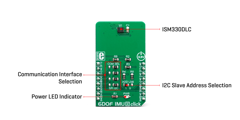
6DOF IMU 8 click supports both SPI and I2C communication interfaces, allowing it to be used with a wide range of different MCUs. The communication interface can be selected by moving SMD jumpers grouped under the COM SEL to an appropriate position (SPI or I2C). The slave I2C address can also be configured by an SMD jumper when the Click board™ is operated in the I2C mode an SMD jumper labeled as ADD LSB is used to set the least significant bit (LSB) of the I2C address. When set to 1, the 7-bit I2C slave address becomes 0b1101011x. If set to 0, the address becomes 0b1101010x. The last digit (x) is the R/W bit.
This Click Board™ uses both I2C and SPI communication interfaces. It is designed to be operated only with up to 3.3V logic levels. Proper conversion of logic voltage levels should be applied, before the Click board™ is used with MCUs operated at 5V.
Specifications
| Type | Motion |
| Applications | 6DOF IMU 8 click can be used for development of different types of motion-based applications, including industrial, IoT, and connected devices, robotics, drones, antenna alignment applications, optical image stabilization, and similar Industry 4.0 related applications. |
| On-board modules | ISM330DLC, a 3D accelerometer and 3D gyroscope with digital output for industrial applications, produced by STMicroelectronics. |
| Key Features | Extensive interrupt engine that can be used to signal a number of recognizable events over two dedicated interrupt pins, high robustness and reliability suitable for industrial use, fully configurable options, two independent sensors allow full 6D sensing… |
| Interface | I2C,SPI |
| Input Voltage | 3.3V |
| Click board size | M (42.9 x 25.4 mm) |
Pinout Diagram
This table shows how the pinout on 6DOF IMU 8 click corresponds to the pinout on the mikroBUS™ socket (the latter shown in the two middle columns).
| Notes | Pin | Pin | Notes | ||||
|---|---|---|---|---|---|---|---|
| Interrupt | IT2 | 1 | AN | PWM | 16 | NC | |
| NC | 2 | RST | INT | 15 | IT1 | Interrupt | |
| SPI Chip Select | CS | 3 | CS | RX | 14 | NC | |
| SPI Clock | SCK | 4 | SCK | TX | 13 | NC | |
| SPI Data OUT | SDO | 5 | MISO | SCL | 12 | SCL | I2C Clock |
| SPI Data IN | SDI | 6 | MOSI | SDA | 11 | SDA | I2C Data |
| Power Supply | 3.3V | 7 | 3.3V | 5V | 10 | NC | |
| Ground | GND | 8 | GND | GND | 9 | GND | Ground |
Onboard Settings And Indicators
| Label | Name | Default | Description |
|---|---|---|---|
| LD1 | PWR | - | Power LED indicator |
| JP1 | ADD LSB | Left | Slave I2C address LSB selection: left position 1, right position 0 |
| JP2-JP5 | COM SEL | Right | Communication interface selection: left position SPI, right position I2C |
Software Support
We provide a library for the 6DOF IMU 8 click on our LibStock page, as well as a demo application (example), developed using MikroElektronika compilers. The demo can run on all the main MikroElektronika development boards.
Library Description
The library performs a control of the 6DOF IMU 8 Click board, which is able to measure the accelerometer, gyroscope, temperature and magnetometer axis data. The full scale range and data rate are adjustable for each measurement. 6DOF IMU 8 Click board has two serial interface, SPI and I2C. There is also a more others settings and configurations which the user can use to set a device for the desired operation mode. For more details check documentation.
Key functions:
void c6dofimu8_getData( T_c6dofimu8_axis *accelOut, T_c6dofimu8_axis *gyroOut, int8_t *tempOut )- Function performs a data reading and all necessary calculations to get accelerometer, gyroscope and temperature data.T_C6DOFIMU8_RETVAL c6dofimu8_setFSR( uint8_t gyro_fsr, uint8_t accel_fsr )- Function selects a measurement full scale range.T_C6DOFIMU8_RETVAL c6dofimu8_setODR( uint8_t gyro_odr, uint8_t accel_odr )- Function selects a measurement output data rate.
Examples description
The application is composed of the three sections :
- System Initialization - Initializes peripherals and pins.
- Application Initialization - Initializes SPI interface and performs a device software reset and configuration.
- Application Task - (code snippet) - Waits until any new data is entered to the data registers and then reads the accelerometer, gyroscope and temperature data which will be converted and calculated to the properly units every 300ms.
void applicationTask()
{
    dataReady = c6dofimu8_getDRDYStatus( _C6DOFIMU8_TEMP_DRDY_MASK | _C6DOFIMU8_G_DRDY_MASK | _C6DOFIMU8_XL_DRDY_MASK );
    while (dataReady == _C6DOFIMU8_EVENT_NOT_DETECTED)
    {
        dataReady = c6dofimu8_getDRDYStatus( _C6DOFIMU8_TEMP_DRDY_MASK | _C6DOFIMU8_G_DRDY_MASK | _C6DOFIMU8_XL_DRDY_MASK );
    }

    c6dofimu8_getData( &accel_data, &gyro_data, &temperature );

    mikrobus_logWrite( "** Accelerometer values :", _LOG_LINE );
    logAxis( &accel_data, &accelUnit[0] );
    mikrobus_logWrite( "", _LOG_LINE );

    mikrobus_logWrite( "** Gyroscope values :", _LOG_LINE );
    logAxis( &gyro_data, &gyroUnit[0] );
    mikrobus_logWrite( "", _LOG_LINE );

    mikrobus_logWrite( "** Temperature value : ", _LOG_TEXT );
    ShortToStr( temperature, text );
    mikrobus_logWrite( text, _LOG_TEXT );
    mikrobus_logWrite( tempUnit, _LOG_LINE );
    mikrobus_logWrite( "-------------------------------------------------", _LOG_LINE );
    mikrobus_logWrite( "", _LOG_LINE );

    Delay_ms( 300 );
}
Additional Functions :
- floatCut - Makes to float values be rounded on two decimal places.
- logAxis - Logs a axis values for the desired measured data on the uart terminal.
The full application code, and ready to use projects can be found on our LibStock page.
Other mikroE Libraries used in the example:
I2CUARTSPI
Additional notes and informations
Depending on the development board you are using, you may need USB UART click, USB UART 2 click or RS232 click to connect to your PC, for development systems with no UART to USB interface available on the board. The terminal available in all MikroElektronika compilers, or any other terminal application of your choice, can be used to read the message.
MIKROSDK
This click board is supported with mikroSDK - MikroElektronika Software Development Kit. To ensure proper operation of mikroSDK compliant click board demo applications, mikroSDK should be downloaded from the LibStock and installed for the compiler you are using.
For more information about mikroSDK, visit the official page.
Downloads
Write a review
Your Name:
Your Review:
Note: HTML is not translated!
Rating:
Bad
Good
Enter the code in the box below:
-
 ₹2,629.00


© 2026, MG Automation Technologies. Powered by MG Super LABS.Find us on Google+
Designed with by Ish Gupta