Color 7 click
Product Code: MIKROE-3062


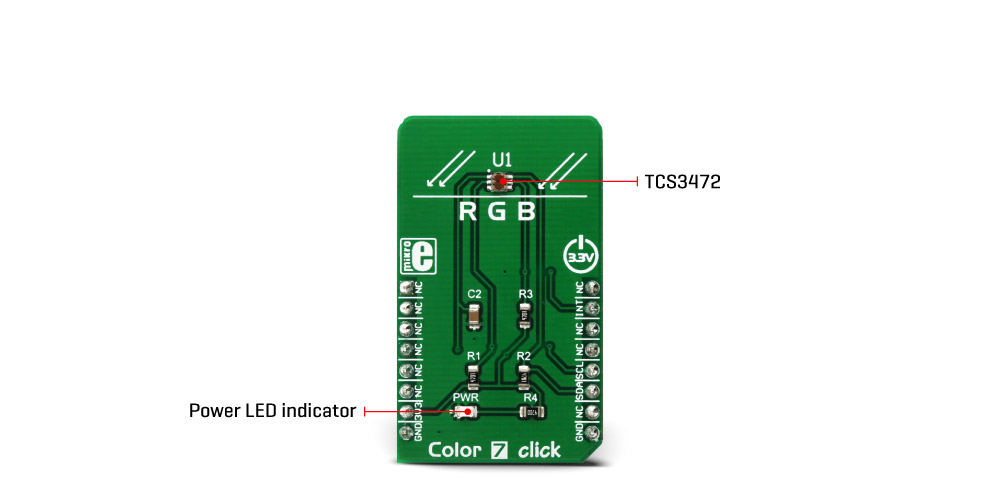
Color 7 click is a very accurate color sensing Click board™ which features the TCS3472 color light to digital converter with IR filter, from ams. It contains a 3x4 matrix of photosensitive elements, which can sense red, green, blue and clear light component. Additional IR resistive coating reduces the influence of the IR component of the light spectrum. Four low noise 16bit ADCs ensure the high dynamic range, making this sensor suitable to be used behind dark glass. This sensor offers a fast I2C interface for the communication with the host MCU. Ability to measure light without the influence of the IR makes this device a good choice for Ambient Light Sensing (ALS).
In addition to high accuracy and sensitivity, this color sensor also offers a programmable interrupt pin, used to trigger an interrupt on the host MCU. This allows more efficient controller firmware to be written. Features, such as the high dynamic range, programmable gain and integration time, very high sensitivity, interrupt pin with programmable events, and more, make this Click board™ an ideal solution for LED lighting color management, ambient light sensing for display backlight control, product color verification and sorting, and other similar applications that require an accurate color and ambient light sensing.
How does it work?
The sensor component used on the Color 6 click is the TCS3472 color light to digital converter with IR filter, from ams. The color sensor is made out of a 4x3 matrix of photosensitive elements - photodiodes, which are placed under red, green, and blue colored filters. One group of photodiodes has no color filter, thus sensing the clear light. All the photodiodes are coated with an IR resistive layer, which prevents the influence of the IR part of the spectrum on the color readings. Besides the color sensing elements, the TCS3472 has four 16bit ADCs that convert the photodiode current into a 16bit value, available for reading. Finally, the TCS3472 IC contains a state machine, which controls the operation of the IC.
After the Power ON reset, the device is set in the low power mode (Sleep mode). An I2C Start condition will wake up the device and it transitions to the Idle state. After checking the content of the Enable register PON bit. If set, the device will resume in Idle mode, and after setting the AEN bit of the Enable register, the sampling cycle is started. Another bit (WEN) determines if the device will start in Wait mode, or it will start the sampling cycle, with the integration time, defined by the user firmware. Integration time affects the sensitivity and the resolution of ADCs. After the conversion is complete, the device returns to idle state, repeating the whole cycle, depending on the states of these bits.
There are two modes of measurement available on this Click board™. It can use the CONT (continuous measurement), or the CMD (single measurement) measurement modes. The CONT mode outputs data continuously, using a time delay determined by the content of the BREAK register, while the CMD mode allows one measurement to be performed per command. After a single measurement is performed, the device can fall back to the Power Down or Standby state, while working in CMD mode. This is determined by the appropriate bits in the configuration registers and allows for a lower power consumption if required by the application.
The interrupt engine allows low and high thresholds to be defined. The conversion value is compared with values set as the low and high threshold, and if any of the threshold values is exceeded, the interrupt event will be generated. The interrupt will assert the INT pin of the IC, routed to the mikroBUS™ INT pin. The interrupt pin will remain asserted until host clears the interrupt flag by the appropriate command. Another interrupt engine feature is the persistence filter. This allows the number of the consecutive threshold exceed occurrences to be made before triggering an interrupt, avoiding erratic or false interrupt triggering. This pin is an open drain topology, and when asserted, it will be driven to a LOW logic state. It is set to a HIGH state when inactive, by the pull-up resistor.
The Click board™ itself uses a very low number of external components. In fact, it only uses a few resistors for pulling the I2C/INT lines to a HIGH logic level when not asserted. The low number of external components simplify the design with this IC, allowing it to be used in a wide range of applications. I2C bus lines are routed to the appropriate mikroBUS™ pins, offering simple and reliable interfacing with the host MCU. Please note that this Click board™ can work only with 3.3V MCUs and it is not 5V tolerant.
The device datasheet contains all the necessary information about the registers and their values. However, the Click board™ comes supported by a library, which contains functions which greatly simplify the development of the applications, cutting time to market.
Specifications
| Type | Optical |
| Applications | It's an ideal solution for LED lighting color management, ambient light sensing for display backlight control, product color verification and sorting, and other similar applications, etc. |
| On-board modules | TCS3472 color light to digital converter with IR filter, from ams sensors company |
| Key Features | High dynamic range, high sensitivity, greatly reduced influence of IR spectrum, programmable analog gain and integration time, low number of external components required. |
| Interface | I2C |
| Input Voltage | 3.3V |
| Click board size | M (42.9 x 25.4 mm) |
Pinout diagram
This table shows how the pinout on Color 7 click corresponds to the pinout on the mikroBUS™ socket (the latter shown in the two middle columns).
| Notes | Pin | Pin | Notes | ||||
|---|---|---|---|---|---|---|---|
| NC | 1 | AN | PWM | 16 | NC | ||
| NC | 2 | RST | INT | 15 | INT | Interrupt | |
| NC | 3 | CS | RX | 14 | NC | ||
| NC | 4 | SCK | TX | 13 | NC | ||
| NC | 5 | MISO | SCL | 12 | SCL | I2C Clock | |
| NC | 6 | MOSI | SDA | 11 | SDA | I2C Data | |
| Power supply | 3.3V | 7 | 3.3V | 5V | 10 | NC | |
| Ground | GND | 8 | GND | GND | 9 | GND | Ground |
Color 7 click electrical specifications
| Description | Min | Typ | Max | Unit |
|---|---|---|---|---|
| ADC resolution | - | 16 | - | bit |
| Gain scaling | 4 | - | 60 | X |
| I2C clock speed | - | - | 400 | kHz |
Onboard settings and indicators
| Label | Name | Default | Description |
|---|---|---|---|
| PWR | PWR | - | Power LED indicator |
Software support
We provide a demo application for Color 6 click on our Libstock page, as well as a demo application (example), developed using MikroElektronika compilers. The demo can run on all the main MikroElektronika development boards.
Library Description
The library initializes and defines the I2C bus driver and drivers that offer a choice for writing data in the register. The library includes functions for configuring the chip for measurement, reading one color ratio and light color value. The color value is calculated by converting the RGBC value to HSL value. The user also has the function color7_getColor() which checks the color of the light.
Key functions:
void color7_writeByte(uint8_t reg, uint8_t _data)- Functions for write one byte in registerfloat color7_getColorValue()- Functions for reading the color value in HSL.uint8_t color7_getColor(float color_value)- Functions for detecting colors.float color7_readColorRatio(uint8_t color)- Functions for reading the color ratio.
Example description
The application is composed of three sections:
- System Initialization - Initializes the I2C module.
- Application Initialization - Initializes the driver init and the configuration chip for measurement.
- Application Task - (code snippet) - Reads the light color and checks which color of the light is detected by the sensor. If the light color is detected, the detected color message is logged on the USB-UART.
void applicationTask()
{
 colorValue = color7_getColorValue();
 isColor = color7_getColor(colorValue);

 switch(isColor)
 {
 case 1:
 {
 mikrobus_logWrite("--- Color: ORANGE ", _LOG_LINE);
 break;
 }
 case 2:
 {
 mikrobus_logWrite("--- Color: RED ", _LOG_LINE);
 break;
 }
 case 3:
 {
 mikrobus_logWrite("--- Color: PINK ", _LOG_LINE);
 break;
 }
 case 4:
 {
 mikrobus_logWrite("--- Color: PURPLE ", _LOG_LINE);
 break;
 }
 case 5:
 {
 mikrobus_logWrite("--- Color: BLUE ", _LOG_LINE);
 break;
 }
 case 6:
 {
 mikrobus_logWrite("--- Color: CYAN ", _LOG_LINE);
 break;
 }
 case 7:
 {
 mikrobus_logWrite("--- Color: GREEN ", _LOG_LINE);
 break;
 }
 case 8:
 {
 mikrobus_logWrite("--- Color: YELLOW ", _LOG_LINE);
 break;
 }
 default:
 {
 break;
 }
 }
 Delay_100ms();
}
The full application code, and ready to use projects can be found on our Libstock page.
Other MikroElektronika libraries used in the example:
- I2C
- UART
Additional notes and information
Depending on the development board you are using, you may need USB UART click, USB UART 2 click or RS232 click to connect to your PC, for development systems with no UART to USB interface available on the board. The terminal available in all MikroElektronika compilers, or any other terminal application of your choice, can be used to read the message.
mikroSDK
This click board is supported with mikroSDK - MikroElektronika Software Development Kit. To ensure proper operation of mikroSDK compliant click board demo applications, mikroSDK should be downloaded from the LibStock and installed for the compiler you are using.
For more information about mikroSDK, visit the official page.
Downloads
mikroBUS™ Standard specificationWrite a review
Your Name:
Your Review:
Note: HTML is not translated!
Rating:
Bad
Good
Enter the code in the box below:
-
 ₹5,149.00


© 2026, MG Automation Technologies. Powered by MG Super LABS.Find us on Google+
Designed with by Ish Gupta