Jrk G2 21v3 USB Motor Controller with Feedback
Product Code: Pololu #3142


Description
This compact motor controller makes closed-loop speed or position (but not both!) control of a brushed DC motor easy, with quick configuration over USB using our free software. It supports five control interfaces: USB, TTL serial, I²C, analog voltage (potentiometer), and hobby radio control (RC). This version offers a 4.5 V to 28 V operating range and can deliver continuous output currents up to 2.6 A(5 A peak) without a heat sink. Male headers and terminal blocks are included but not soldered, allowing for custom installations.
Overview
With integrated support for analog voltage or tachometer (frequency) feedback, the second-generation G2 family of Jrk motor controllers makes it easy to add closed-loop control of speed or position (but not both!) of a single brushed DC motor to a variety of projects. These versatile, general-purpose modules support five different control interfaces: USB for direct connection to a computer, TTL serial and I²C for use with a microcontroller, RC hobby servo pulses for use in an RC system, and analog voltages for use with a potentiometer or analog joystick. They also offer many settings that can be configured using our free configuration software utility for Windows, Linux, and macOS. This software simplifies initial setup of the device and allows for in-system testing and monitoring of the controller via USB (a micro-B USB cable is required to connect the Jrk G2 to a computer).
 |
Main features of the Jrk G2 family
- Easy open-loop or closed-loop control of one brushed DC motor
- A variety of control interfaces:
- USB for direct connection to a computer
- TTL serial operating at 5 V for use with a microcontroller
- I²C for use with a microcontroller
- RC hobby servo pulses for use in an RC system
- Analog voltage for use with a potentiometer or analog joystick
- Feedback options:
- Analog voltage (0 V to 5 V), for making a closed-loop servo system
- Frequency, for closed-loop speed control using pulse counting (for higher-frequency feedback) or pulse timing (for lower-frequency feedback)
- None, for open-loop speed control
- Note: the Jrk does not support using quadrature encoders for position control
- Ultrasonic 20 kHz PWM for quieter operation (can be configured to use 5 kHz instead)
- Simple configuration and calibration over USB with free configuration software utility (for Windows, Linux, and macOS)
- Configurable parameters include:
- PID period and PID coefficients (feedback tuning parameters)
- Maximum current
- Maximum duty cycle
- Maximum acceleration and deceleration
- Error response
- Input calibration (learning) for analog and RC control
- Optional CRC error detection eliminates communication errors caused by noise or software faults
- Reversed-power protection
- Field-upgradeable firmware
- Optional feedback potentiometer disconnect detection
 |
|
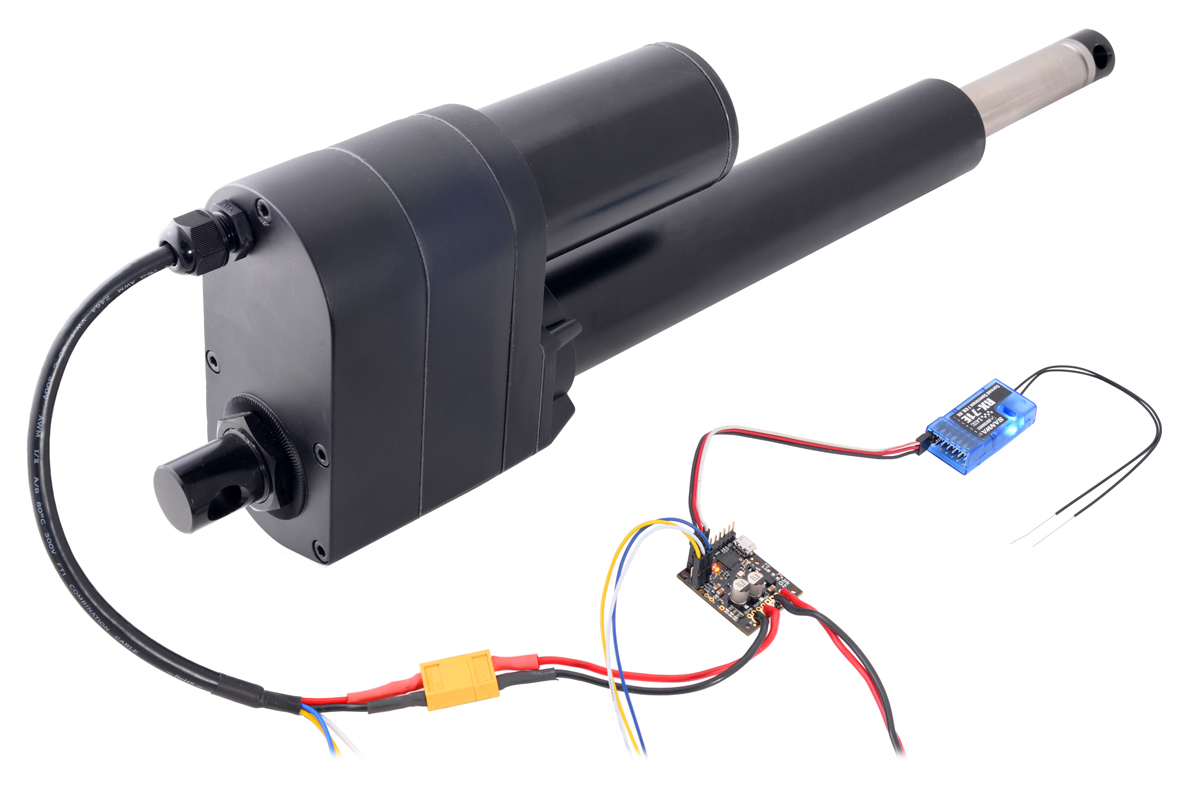
Pololu Jrk G2 18v19 USB Motor Controller with Feedback controlling an industrial-duty linear actuator with an RC receiver. |
|---|
 |
|
Pololu Jrk G2 18v27 USB Motor Controller with Feedback controlling a high-power motor from USB. |
|---|
Details for item #3142
 |
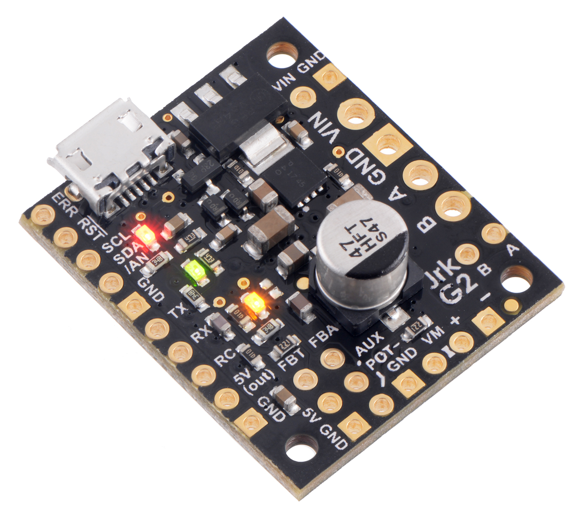
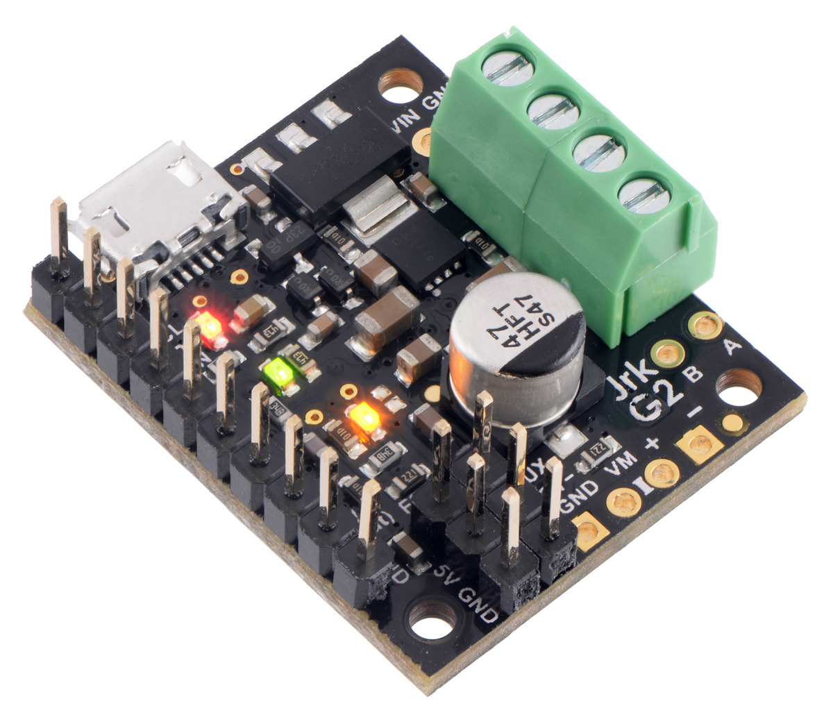
The Jrk G2 21v3 operates from 4.5 V to 28 V and can deliver a continuous output current of 2.6 A (5 A peak) without a heat sink. The controller supports transient operation (< 500 ms) up to 40 V, and the maximum recommended nominal battery voltage is 24 V. This version has header pins and terminal blocks included but not soldered, so soldering is required to use it.
|
|
A version is also available that requires no soldering to use as the terminal blocks and main header pins are already installed.
Included hardware
|
|
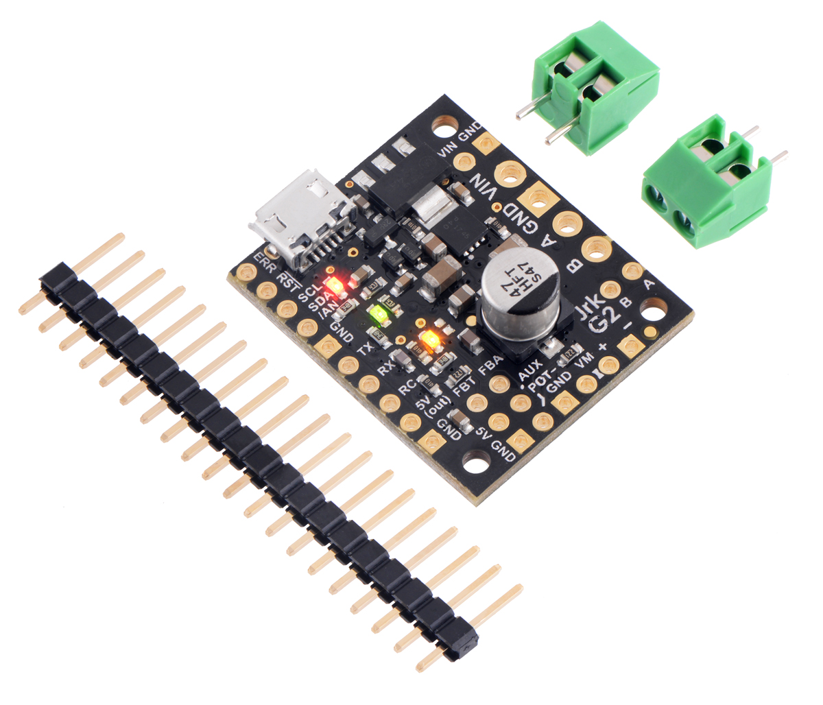
The Jrk ships with a 0.1″ breakaway male header strip and two 2-pin 3.5mm terminal blocks. You can solder the terminal blocks to the four large through-holes to make your motor and motor power connections (see our short video on terminal block installation), or you can solder a couple of 2-pin pieces of the 0.1″ header strip into the smaller through-holes above and below these larger holes.
Pieces from the 0.1″ header strip can be soldered into the small holes on the logic connection side of the board to enable use with solderless breadboards, perfboards, or 0.1″ connectors. For the most compact installation, you can just solder wires directly to the holes.
Note: A USB A to micro-B cable (not included) is required to connect the Jrk G2 to a computer for initial configuration.
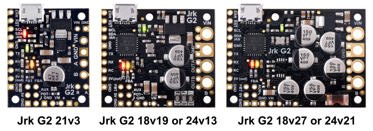
Comparison to the original Jrk motor controllers
The Jrk G2 family features a number of improvements compared to our original two Jrk motor controllers (21v3 and 12v12). Most importantly, the Jrk G2 controllers support both higher operating voltages and larger output currents while being even more compact than their predecessors. Other new features include:
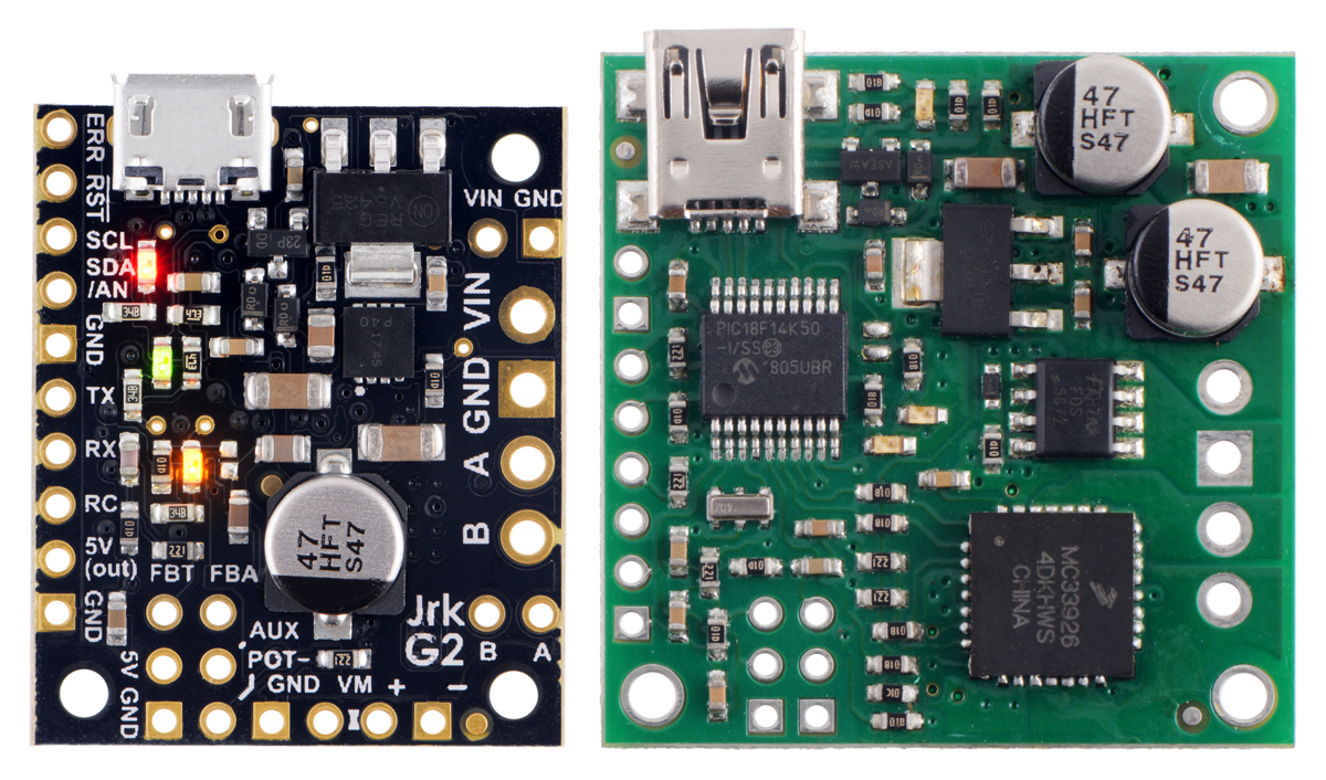 |
|
Comparison of the newer Jrk G2 21v3 (black PCB) with the original Jrk 21v3 (green PCB). |
|---|
- Configurable hardware current limiting on higher-power versions – the motor drivers on the Jrk G2 18v19, 18v27, 24v13, and 24v21 use current chopping to actively limit the motor current when it exceeds a software-configurable threshold (the Jrk G2 21v3 has fixed hardware current limiting and optional software current limiting)
- More accurate speed control at low tachometer frequencies
- I²C interface provides an additional control option
- VIN measurement capability allows monitoring of battery or power supply
- USB Micro-B connector (instead of Mini-B as on the original Jrk controllers)
- Configurable deceleration limiting (the original Jrks just supported configurable acceleration limiting)
- PID coefficients can now be adjusted on the fly over the serial, I²C, and USB interfaces
The Jrk G2 controllers are not drop-in replacements for the original Jrk controllers because of differences in their form factors and pin arrangements, although wiring changes should be straightforward. The Jrk G2 serial protocol is compatible with (and generally a superset of) the original Jrk serial protocol, so in many cases, serial interface software running on a microcontroller or computer will not need to be modified to work with a Jrk G2.
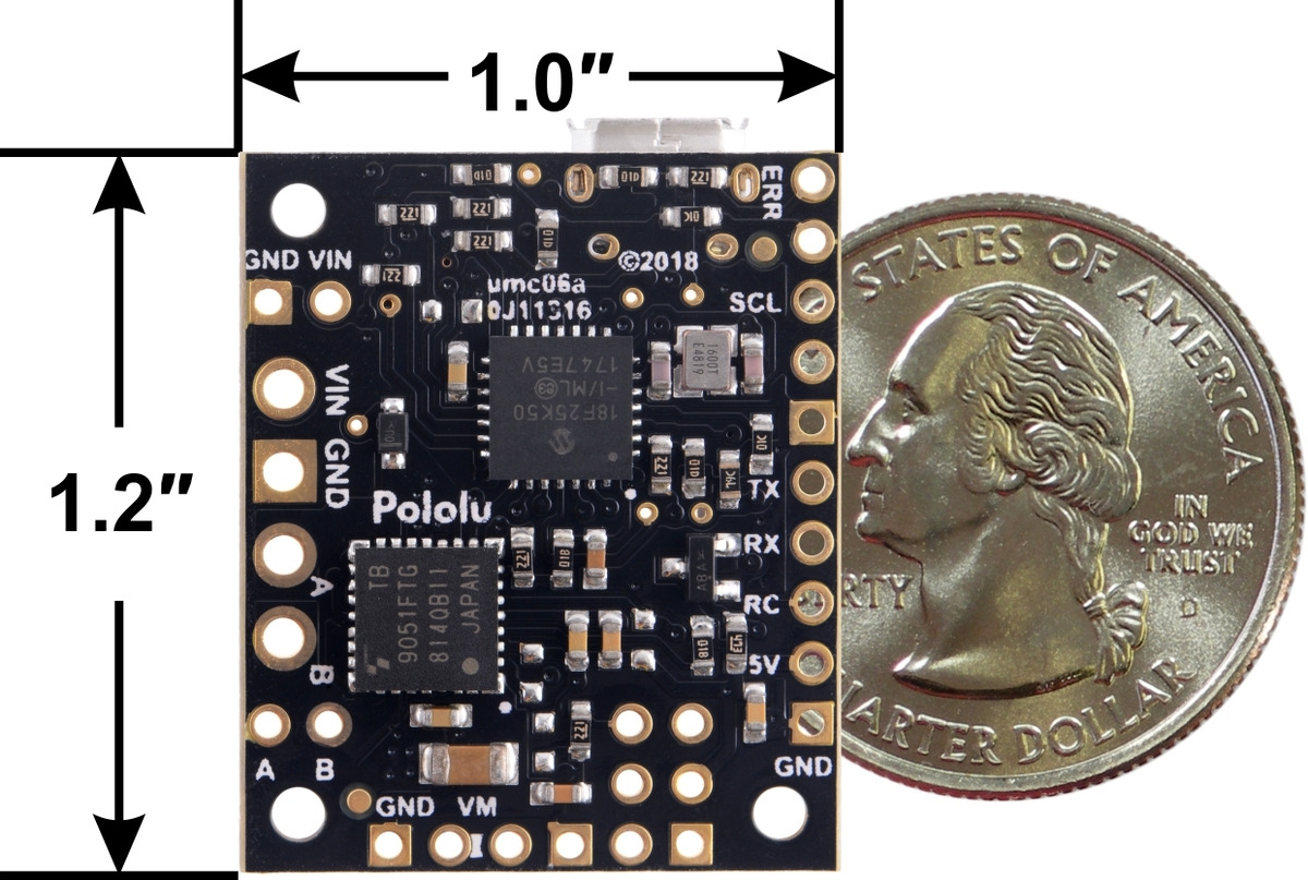
Dimensions
| Size: | 1.2″ × 1.0″ × 0.3″1 |
|---|
General specifications
| Motor channels: | 1 |
|---|---|
| Control interface: | USB; non-inverted TTL serial; I²C; RC servo pulses; analog voltage |
| Minimum operating voltage: | 4.5 V2 |
| Maximum operating voltage: | 28 V3 |
| Continuous output current per channel: | 2.6 A4 |
| Maximum PWM frequency: | 20 kHz |
| Reverse voltage protection?: | Y |
| Version: | G2 21v3 (28 V max, 2.6 A max continuous) |
| Connectors soldered?: | N |
Notes:
1. Without included hardware.
2. Powering the Jrk G2 21v3 with a supply voltage between 4.5 V and 5.5 V might cause its logic voltage to be lower than normal, which could affect operation. See the user’s guide for more information.
3. Transient operation (< 500 ms) up to 40 V.
4. Typical results at room temperature running at 90% duty cycle with VIN > 8 V. Operation from 4.5 V to 8 V reduces maximum current output.
Write a review
Your Name:
Your Review:
Note: HTML is not translated!
Rating:
Bad
Good
Enter the code in the box below:
-
 ₹14,829.00

© 2025, MG Automation Technologies. Powered by MG Super LABS.Find us on Google+
Designed with by Ish Gupta