Keylock click
Product Code: MIKROE-2564


Keylock click carries a processed sealed key lock mechanism that can be set in three different positions. The click is designed to run on either 3.3V or 5V power supply. It communicates with the target microcontroller over the PWM, INT, and AN pin on the mikroBUS™ line.
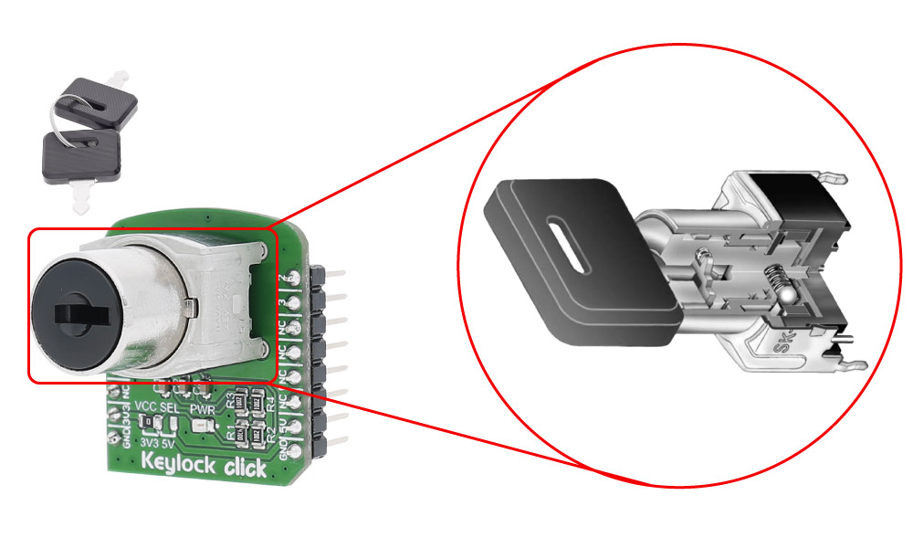
The key can be removed from the lock in any of the three positions. The package contains two keys and one protective cap.
Keylock features
The contact mechanism provides unequaled logic-level reliability and smoother, positive detent actuation.
Detent mechanism, with its spring-operated steel ball, gives crisp, positive action for accurate switch setting.
Specifications
| Type | Joystick |
| Applications | Use the three different positions of the mechanism to turn applications on or off, for home security applications, for industrial equipment, etc. |
| On-board modules | Keylock switch with 3 positions |
| Interface | GPIO |
| Input Voltage | 3.3V or 5V |
| Click board size | S (28.6 x 25.4 mm) |
Pinout diagram
This table shows how the pinout on Keylock click corresponds to the pinout on the mikroBUS™ socket (the latter shown in the two middle columns).
| Notes | Pin | Pin | Notes | ||||
|---|---|---|---|---|---|---|---|
| Output position 1 | 1 | 1 | AN | PWM | 16 | 2 | Output position 2 |
| NC | 2 | RST | INT | 15 | 3 | Output position 3 | |
| NC | 3 | CS | TX | 14 | NC | ||
| NC | 4 | SCK | RX | 13 | NC | ||
| NC | 5 | MISO | SCL | 12 | NC | ||
| NC | 6 | MOSI | SDA | 11 | NC | ||
| Power supply | +3.3V | 7 | 3.3V | 5V | 10 | +5V | Power supply |
| Ground | GND | 8 | GND | GND | 9 | GND | Ground |
Programming
Code examples for Keylock click, written for MikroElektronika hardware and compilers are available on Libstock.
Code snippet
This is a simple example of how Keylock click works, depending on the state of the Keylock click the appropriate position will be detected.
01 uint8_t state;
02 char txt[20];
03
04 void systemInit()
05 {
06     ANCON0 = 0x00;
07     ANCON1 = 0x00;
08     ANCON2 = 0x00;
09    UART1_Init(9600);
10 }
11
12 void Keylock_Init()
13 {
14     KEYLOCK_STATE_1_Direction = 1;
15     KEYLOCK_STATE_2_Direction = 1;
16     KEYLOCK_STATE_3_Direction = 1;
17 }
18
19 void Keylock_Task()
20 {
21     state =  KEYLOCK_STATE_1*1 + KEYLOCK_STATE_2*2 + KEYLOCK_STATE_3*3;
22     UART1_Write_text("Keylock is in state:");
23     IntToStr(state,txt) ;
24     UART1_Write_Text(txt);
25     UART1_Write_Text( "rn" );
26     delay_ms(500);
27 }
28
29 void main()
30 {
31     systemInit();
32     Keylock_Init();
33
34    while( 1 )
35     {
36             Keylock_Task();
37     }
38 }
Downloads
mikroBUS™ Standard specificationKey lock mechanism specifications
Keylock click schematic
Write a review
Your Name:
Your Review:
Note: HTML is not translated!
Rating:
Bad
Good
Enter the code in the box below:
-
 ₹26,149.00


© 2026, MG Automation Technologies. Powered by MG Super LABS.Find us on Google+
Designed with by Ish Gupta