MIC24045 click
Product Code: MIKROE-2574


MIC24045 click carries MIC24045 I2C-programmable, high-efficiency, wide input range, 5A synchronous step-down regulator from Microchip. The click is designed to run on either 3.3V or 5V power supply. It communicates with the target microcontroller over I2C interface with additional functionality provided by the following pins on the mikroBUS™ line: RST, INT.
MIC24045 regulator features
The MIC24045 is a digitally programmable, 5A valley current-mode controlled regulator featuring an input voltage range from 4.5V to 19V.
The MIC24045 is perfectly suited for multiple voltage rail application environments, typically found in computing and telecommunication systems.
Thermal Warning and Thermal Shutdown
The MIC24045 has a thermal shutdown protection that prevents operation at excessive temperature. The thermal shutdown threshold is typically set at +160°C with a hysteresis of +25°C.
The MIC24045 features a Thermal Warning flag that is readable through the I2C interface (register polling is needed). The Thermal Warning flag signals the approaching of thermal shutdown, so that appropriate system-level countermeasures can be undertaken.
How it works
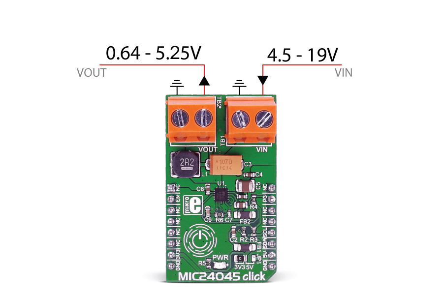
The click is designed to lower the voltage on the input from 4.5V-19V to 0.64V-5.25V. The same voltage is used for powering the MCP24045 IC (TB1 and TB2 connectors).
Specifications
| Type | Boost |
| Applications | Servers, Data Storage, Routers and Base Stations, FPGAs, DSP and Low-Voltage ASIC Power |
| MCU | MIC24045 regulator |
| Key Features | 4.5V to 19V Input Voltage Range, 5A (maximum) Output Current, Switching Frequency: 310 kHz, 400 kHz, 500 kHz, 570 kHz, 660 kHz, 780 kHz, 1 MHz, 1.2 MHz |
| Interface | I2C,GPIO |
| Input Voltage | 3.3V or 5V |
| Compatibility | mikroBUS |
| Click board size | M (42.9 x 25.4 mm) |
Pinout diagram
This table shows how the pinout on MIC24045 click corresponds to the pinout on the mikroBUS™ socket (the latter shown in the two middle columns).
| Notes | Pin | Pin | Notes | ||||
|---|---|---|---|---|---|---|---|
| NC | 1 | AN | PWM | 16 | NC | ||
| Precision Enable Input Pin | ENABLE | 2 | RST | INT | 15 | PG | Power Good Open-Drain Output Pin |
| NC | 3 | CS | TX | 14 | NC | ||
| NC | 4 | SCK | RX | 13 | NC | ||
| NC | 5 | MISO | SCL | 12 | I2C SCL | I2C Clock Input Pin | |
| NC | 6 | MOSI | SDA | 11 | I2C SDA | I2C Data Input/Output Pin | |
| Power supply | +3.3V | 7 | 3.3V | 5V | 10 | +5V | Power supply |
| Ground | GND | 8 | GND | GND | 9 | GND | Ground |
Maximum ratings
| Description | Min | Typ | Max | Unit |
|---|---|---|---|---|
| Input Range | 4.5 | 19 | V | |
| Externally Applied Analog and Drivers Supply Voltage | 4.5 | 5.5 | V | |
| Enable Voltage (VEN) | VDDA | V | ||
| Power-Good (PG) Pull-up Voltage (VPU_PG) | 0 | 5.5 | V | |
| Output Current | 5 | A | ||
| Junction Temperature | -40 | 120 | °C |
Programming
Code examples for MIC24045 click, written for MikroElektronika hardware and compilers are available on Libstock.
Code snippet
The following code snippet calls initialization functions, and then slowly decrements the voltage from maximum value down to the minimum.
01 void main()
02 {
03    system_init();
04    mic_24045_init(0x50);
05    Delay_ms (100);
06    i = 21;
07    while (i)
08    {
09            write_1 = i*0.25;
10            mic_24045_write_vout (write_1);
11            GPIOC_ODR = 0x04;        /* Sets EN pin to 1 */
12            Delay_ms (1000);
13
14            read_2 = mic_24045_read_vout ();
15            FloatToStr (read_2, &uart_text);
16
17            if (read_2 > 1)
18               uart_text [5] = 0;
19
20            UART_Write_Text ("rn");
21            UART_Write_Text (uart_text);
22
23         GPIOC_ODR = 0x00;
24            Delay_ms (1000);
25         i--;
26    }
27 }
Downloads
mikroBUS™ Standard specificationMIC24045 datasheet
MIC24045 click schematic
Write a review
Your Name:
Your Review:
Note: HTML is not translated!
Rating:
Bad
Good
Enter the code in the box below:
-
 ₹2,309.00


© 2026, MG Automation Technologies. Powered by MG Super LABS.Find us on Google+
Designed with by Ish Gupta