7x10 B click
Product Code: MIKROE-2789


The click communicates with the target MCU through the mikroBUS™ SPI interface (SCK, SDO, SDI), with additional functionality provided by R CLK, MR#, LATCH and R RST pins. 7x10 B click is designed to use either a 3.3V or a 5V power supply.
How the click works
7x10 B click is essentially a dual character display capable of showing letters, numbers, and characters in more readable typefaces since the 7x5 resolution is the standard one for displaying ASCII characters. This type of resolution is more readable than the 14-segment display.
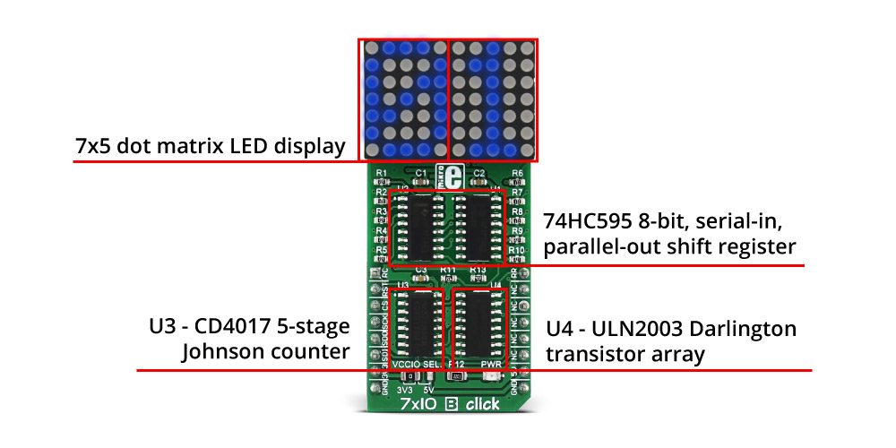
The dot matrix can also show scrolling text, thus fitting longer messages in small space. Two 74HC595 8-bit shift registers are used for driving the columns of the LED matrix separately. The 74HC595 is a 8-bit, serial-in, parallel-out shift register. The rows of the LED are connected to the decoded outputs of CD4017 through ULN2003. CD4017 is a 5-stage Johnson counter and ULN2003 is a high-voltage, high-current Darlington transistor array. The Johnson counter (CD4017) performs the necessary LED multiplex and the current amplification that's needed for driving the LEDs is performed by a Darlington Transistor array.
Specifications
| Type | LED Matrix |
| Applications | 7x5 dot matrix text display for user interfaces, for example on vending machines |
| On-board modules | Matrix of 70 blue LEDs driven by a pairs of 8-bit serial-in, parallel-out shift registers, a Darlington Transistor array and a Johnson counter |
| Key Features | Displays letters in highly readable format, scrolling text capability |
| Interface | GPIO,SPI |
| Input Voltage | 3.3V or 5V |
| Click board size | L (57.15 x 25.4 mm) |
Pinout diagram
This table shows how the pinout on 7x10 B click corresponds to the pinout on the mikroBUS™ socket (the latter shown in the two middle columns).
| Notes | Pin | Pin | Notes | ||||
|---|---|---|---|---|---|---|---|
| CD4017 clock pin | RC | 1 | AN | PWM | 16 | RR | CD4017 reset pin |
| 74HC595 reset | RST | 2 | RST | INT | 15 | NC | |
| Latch of 74HC595 | CS | 3 | CS | TX | 14 | NC | |
| SPI clock pin | SCK | 4 | SCK | RX | 13 | NC | |
| SPI slave data out pin | SDO | 5 | MISO | SCL | 12 | NC | |
| SPI slave data in pin | SDI | 6 | MOSI | SDA | 11 | NC | |
| Power supply | +3.3V | 7 | 3.3V | 5V | 10 | +5V | Power supply |
| Ground | GND | 8 | GND | GND | 9 | GND | Ground |
Jumpers and settings
| Designator | Name | Default Position | Default Option | Description |
|---|---|---|---|---|
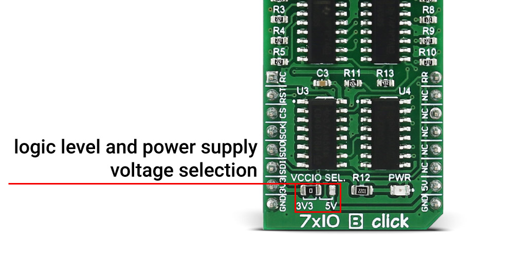
| JP1 | VCCIO SEL. | Left | 3V3 | Logic level voltage and power supply selection 3V3/5V, left position 3V3, right position 5V |
JP1 - this jumper allows you to select the logic level voltage for the communication lines and power supply voltage. If it's in the left position then the logic level voltage and power supply from the mikroBUS™ is 3.3V. If the jumper is in the right position the logic level voltage and power supply from the mikroBUS™ is 5V. Jumper J1 is soldered in 3.3V position by default.
Maximum ratings
| Description | Min | Typ | Max | Unit |
|---|---|---|---|---|
| Operating Power-Supply Voltage | 3.3 | 3.3 | 5 | V |
LEDs, Buttons, Switches, Connectors, etc.
| Designator | Name | Type | Description |
|---|---|---|---|
| LD1 | PWR | LED | Power LED, lights green when the power supply is established properly. |
Software Support
We provide a library for the 7x10 B click on our LibStock page, as well as a demo application (example), developed using MikroElektronika compilers. The demo application can run on all the main MikroElektronika development boards.
Note: You can use our free supporting software - GLCD Font Creator, and make personalized fonts, symbols, and icons for the LED matrix onboard the click. Create fonts and symbols from scratch, or by importing existing fonts on your system. It lets you modify and adjust them for your needs, apply effects and finally export them as source code for use in mikroC, mikroBasic or mikroPascal compilers.
Library Description
The library carries all functions necessary for complete control over the 7x10 B click. There is also an additional font header file which carries 5x7 letter definitions.
Key functions
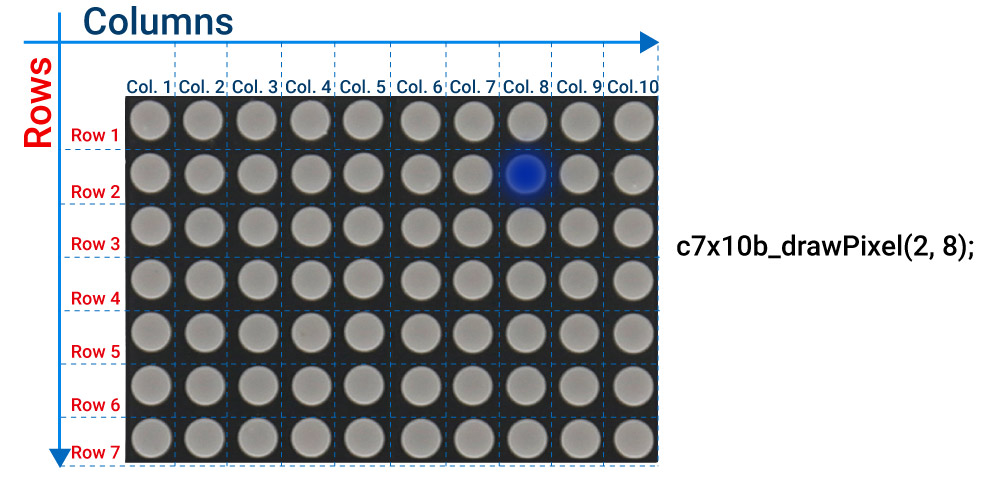
bool c7x10b_refreshDisplay( void )- Refreshes the display; this function should be called upon as frequently as possible.void c7x10b_drawPixel( uint8_t row, uint8_t col )- Draws single pixel on the desired location.
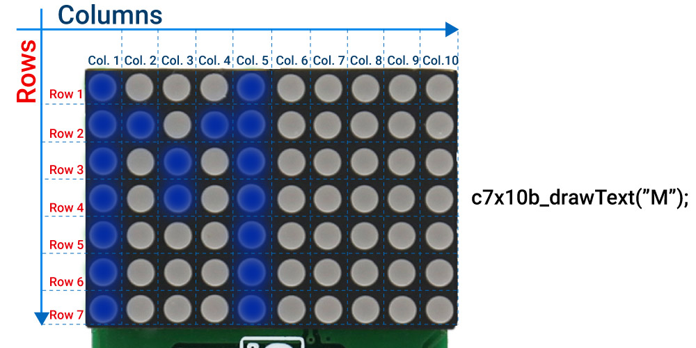
void c7x10b_drawText( char *text )- Writes the text; The first character is placed on the first LED matrix, and the second one is placed on the second LED matrix (if there is more than one character).
The example also carries additional functions for GPIO control which are provided during driver initialization. These functions are necessary and the implementation depends on the type of development system that is used.
Examples Description
The application is composed of three sections :
- System Initialization - Initializes GPIO and SPI peripheral
- Application Initialization - Default driver initialization
- Application Task - (code snippet) a demonstration of the main functions of the library. First, the text "MikroElektronika" is scrolled, then the countdown from 0 to 30. And finally random lighting up of the LEDs - using the function
c7x10b_drawPixel.
void applicationTask()
{
    bool ind;
    static bool called = false;
    int i, j;

    c7X10b_clearDisplay();
    if ( !called )
    {
        c7X10b_drawText( "  MikroElektronika" );
        c7X10b_scrollEnable( _C7X10B_SPEED_MED );
        called = true;
    }
    do
    {
        ind = c7X10b_refreshDisplay();
        c7X10b_tick();
        Delay_ms( 10 );

    } while( ind );

    called = false;

    for( i = 0; i < 11; ++i )
    {
        c7x10b_clearDisplay();
        c7x10b_drawNumber( i );
        for( j = 0; j < 30; ++j )
        {
            c7X10b_refreshDisplay();
            Delay_ms( 10 );
        }
    }
    c7x10b_clearDisplay();
    c7x10b_drawPixel( 6, 3 );
    c7x10b_drawPixel( 6, 8 );
    c7x10b_drawPixel( 2, 3 );
    c7x10b_drawPixel( 2, 8 );
    for( j = 0; j < 100; ++j )
    {
        c7x10b_refreshDisplay();
        Delay_ms( 10 );
    }

}
The full application code and libraries are available for download on our LibStock page.
Downloads
mikroBUS™ Standard specificationsLearn: 7x10 LEDs, magic vision
Write a review
Your Name:
Your Review:
Note: HTML is not translated!
Rating:
Bad
Good
Enter the code in the box below:
-
 ₹1,889.00


© 2026, MG Automation Technologies. Powered by MG Super LABS.Find us on Google+
Designed with by Ish Gupta