Opto Encoder click


Opto Encoder click is a linear incremental optical sensor/encoder click which can be used for the movement or rotation encoding. Encoders of this type are widely used for many applications, which involve precise detection of the position, speed, or rotational angle of an object. Rotary encoders are often used for various types of controllers on many different devices. Whether it be a rotary encoder knob controller or an angle encoder on a motor shaft, the principle is the same - it includes an optical sensor, just like the one found on Opto Encoder click.
This Click board™ features an optical sensor in a tall dome design, which allows more physical space, even for a vertical signal encoding. It can be used as an optical sensor in automotive applications, motion, speed, and direction sensor, for precise motor shaft positioning applications, knob encoder applications, and similar applications, where dual channel optical sensing can be utilized.
How does it work?
The optical sensor used on the Opto Encoder click is the TCUT1600X01, a tall dome dual channel transmissive optical sensor with phototransistor outputs from Vishay. This sensor is equipped with one infrared LED with the wavelength of 950nm, and two phototransistors. These phototransistors are positioned behind two small slits on the sensor, on the opposite side of the LED. They form two separate channels. When the transistors get illuminated by the LED, they become conductive. The collectors of these transistors are connected to the same pin, while their emitters are routed to two separate output pins of the TCUT1600X01 - E1 and E2. This allows the activity on both channels to be detected by the host MCU.
Since the signals of these two output channels are not enough to drive pins on a host MCU, the Click board™ features two additional MOSFETs. These MOSFETs are also used to drive two additional LEDs, which indicate activity of each channel. E1 and E2 pins are routed to the MOSFET gate pins, while the MOSFET drains are routed to the mikroBUS™ PWM and INT pins. These pins are pulled to a LOW logic level by the pull-down resistors, to avoid floating.
Signal encoding itself is done by the host MCU. Having two optical sensing channels, Opto Encoder click has the ability of both speed and direction encoding. The most common usage is encoding of the step motor position: a cylinder with slits is physically mounted above the sensor so that the LED can illuminate the phototransistors only through these slits. By rotating this cylinder, the light beam will be blocked periodically. The single sensor output will be a pulse train, while the cylinder is rotating. Having two photo sensors physically distanced by a small amount, allows the pulse signal of the first sensor to be either delayed or expedited with respect to the pulse on the second sensor, depending on the rotational direction.
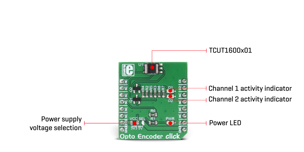
This Click board™ can operate with either 3.3V or 5V, allowing to be operated on both 3.3V and 5V MCUs. The onboard SMD jumper, labeled as the VCC SEL is used to select the operating voltage of the Opto Encoder click.
Provided Click board™ library offers easy to use functions that can be used to get the encoder position. The provided example application demonstrates the usage of these functions and can be used for further custom development.
Specifications
| Type | Optical |
| Applications | Automotive optical sensors, accurate position sensor for encoder, sensor for motion, speed, and direction, etc. |
| On-board modules | TCUT1600X01 Tall Dome Dual Channel Transmissive Optical Sensor with Phototransistor Outputs |
| Key Features | The Opto Encoder click features a precise detection of the position, speed, or rotational angle of an object. It is able to detect the direction of the movement since it features two photo-sensing elements. |
| Input Voltage | 3.3V or 5V |
| Click board size | S (28.6 x 25.4 mm) |
Pinout diagram
This table shows how the pinout on Opto Encoder click corresponds to the pinout on the mikroBUS™ socket (the latter shown in the two middle columns).
| Notes | Pin | Pin | Notes | ||||
|---|---|---|---|---|---|---|---|
| NC | 1 | AN | PWM | 16 | O1 | O1 Output | |
| NC | 2 | RST | INT | 15 | O2 | O2 Output | |
| NC | 3 | CS | RX | 14 | NC | ||
| NC | 4 | SCK | TX | 13 | NC | ||
| NC | 5 | MISO | SCL | 12 | NC | ||
| NC | 6 | MOSI | SDA | 11 | NC | ||
| Power supply | +3.3V | 7 | 3.3V | 5V | 10 | +5V | |
| Ground | GND | 8 | GND | GND | 9 | GND | Ground |
Opto Encoder click specifications
| Description | Min | Typ | Max | Unit |
|---|---|---|---|---|
| IR LED forward voltage | 1 | 1.2 | 1.4 | V |
| Switching Rise Time (5V) | - | 9 | 150 | µs |
| Switching Fall Time (5V) | - | 16 | 150 | µs |
Onboard settings and indicators
| Label | Name | Default | Description |
|---|---|---|---|
| JP1 | - | Left | Power Supply Voltage Selection: Left position 3V3, right position 5V |
| LD1 | PWR | Power indication LED | |
| O1 | O1 | Channel 1 activity indication LED | |
| O2 | O2 | Channel 2 activity indication LED |
Software support
We provide a library for Opto Encoder click on our Libstock page, as well as a demo application (example), developed using MikroElektronika compilers and mikroSDK. The provided click library is mikroSDK standard compliant. The demo application can run on all the main MikroElektronika development boards.
Library Description
This library contains basic functions that will allow you to read the sensor.
Key functions:
void optoencoder_init(); - Initialization for the click board.
uint8_t optoencoder_getO1(); - Read the state of encoder channel 1.
uint8_t optoencoder_getO2(); - Read the state of the encoder channel 2.
int16_t optoencoder_getPosition(); - Return's the current position.
Examples Description
- The application is composed of three sections:
- System Initialization - Initializes PWM pin and INT pin as INPUT.
- Application Initialization - Initializes Driver init and opto encoder init.
- Application Task - (code snippet) - Detects the change of step and logs to USB UART number of stepped steps.
void applicationTask()
{
 newStep = optoencoder_getPosition();

 if(oldStep != newStep)
 {
 IntToStr(newStep, text);
 mikrobus_logWrite(" Step: ", _LOG_TEXT);
 mikrobus_logWrite(text, _LOG_LINE);
 oldStep = newStep;
 }
}
The full application code, and ready to use projects can be found on our LibStock page.
Other mikroE Libraries used in the example:
- UART Library
- Conversions Library
- C_String Library
Additional notes and information
Depending on the development board you are using, you may need USB UART click, USB UART 2 click or RS232 click to connect to your PC, for development systems with no UART to USB interface available on the board. The terminal available in all MikroElektronika compilers, or any other terminal application of your choice, can be used to read the message.
mikroSDK
This click board is supported with mikroSDK - MikroElektronika Software Development Kit. To ensure proper operation of mikroSDK compliant click board demo applications, mikroSDK should be downloaded from the LibStock and installed for the compiler you are using.
For more information about mikroSDK, visit the official page.
Downloads
mikroBUS™ Standard specificationLibStock: mikroSDK
TCUT1600X01 datasheet
Opto Encoder click schematic
Opto Encoder click: 2D and 3D files
Enter the code in the box below: