Pololu 5V, 5A Step-Down Voltage Regulator D24V50F5
Product Code: Pololu #2851


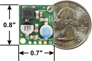
This small synchronous switching step-down (or buck) regulator takes an input voltage of up to 38 V and efficiently reduces it to 5 V. The board measures only 0.7″ × 0.8″, but it allows a typical continuous output current of up to 5 A. Typical efficiencies of 85% to 95% make this regulator well suited for high-power applications like powering motors or servos. High efficiencies are maintained at light loads by dynamically changing the switching frequency, and an optional shutdown pin enables a low-power state with a current draw of a few hundred microamps.
This step-down (buck) regulator generates a fixed 5 V output from input voltages up to 38 V. It is a switching regulator (also called a switched-mode power supply (SMPS) or DC-to-DC converter) and has a typical efficiency between 85% to 95%. The available output current is a function of the input voltage and efficiency (see the Typical Efficiency and Output Current section below), but the output current can typically be as high as 5 A. The regulator has a typical quiescent current draw of less than 1 mA, and the ENABLE pin can be used to put the board in a low-power state that reduces the quiescent current to approximately 10 µA to 20 µA per volt on VIN.
For lower-power applications, we carry a slightly smaller, pin-compatible version of this regulator that has a typical maximum output current of 2.5 A.
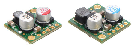
Side-by-side comparison of the 2.5A D24V25Fx (left) and
5A D24V50Fx (right) step-down voltage regulators.
Two larger, higher-power versions of this regulator are also available: one with a typical maximum output current of 6 A, and the other with a typical maximum output current of 9 A. The higher-power versions also have a few additional features, like a “power good” signal and the ability to lower their output voltage, and they include optional terminal blocks for easy removable connections.
This regulator has built-in reverse-voltage protection, short-circuit protection, thermal shutdown, a soft-start feature that reduces inrush current, and an under-voltage lockout.
Features
- Input voltage: 6 V to 38 V (see below for more details on the regulator’s dropout voltage, which affects the low end of the operating range)
- Fixed 5 V output (with 4% accuracy)
- Typical maximum continuous output current: 5 A
- Integrated reverse-voltage protection, over-current protection, over-temperature shutoff, soft-start, and under-voltage lockout
- Typical efficiency of 85% to 95%, depending on input voltage and load; the switching frequency automatically changes at light loads to maintain high efficiencies
- 700 μA typical no-load quiescent current; can be reduced to 10 µA to 20 µA per volt on VIN by disabling the board
- Compact size: 0.7″ × 0.8″ × 0.35″ (17.8 mm × 20.3 mm × 8.8 mm)
- Two 0.086″ mounting holes for #2 or M2 screws
Using the regulator
Connections
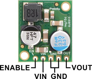
This buck regulator has five connection points for four different connections: enable (EN), input voltage (VIN), 2x ground (GND), and output voltage (VOUT).
The input voltage, VIN, powers the regulator and can be supplied with voltages up to 38 V. The effective lower limit of VIN is VOUT plus the regulator’s dropout voltage, which varies approximately linearly with the load from around 700 mV to around 1.5 V (see below for a graph of the dropout voltages as a function of the load).
The regulator is enabled by default: a 100 kΩ pull-up resistor on the board connects the ENABLE pin to reverse-protected VIN. The ENABLE pin can be driven low (under 0.6 V) to put the board into a low-power state. The quiescent current draw in this sleep mode is dominated by the current in the pull-up resistor from ENABLE to VIN and by the reverse-voltage protection circuit, which will draw between 10 µA and 20 µA per volt on VIN when ENABLE is held low. If you do not need this feature, you should leave the ENABLE pin disconnected.
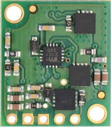
Pololu 5A Step-Down Voltage Regulator D24V50Fx Pololu 5A Step-Down Voltage Regulator D24V50Fx, bottom view.
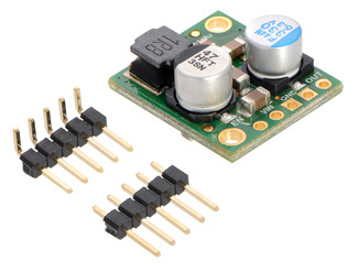
with included hardware
The five connection points are labeled on the top of the PCB and are arranged with a 0.1″ spacing for compatibility with solderlessbreadboards, connectors, and other prototyping arrangements that use a 0.1″ grid. Either the included 5×1 straight male header strip or the 5×1 right angle male header strip can be soldered into these holes. For the most compact installation, you can solder wires directly to the board.
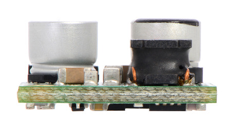
| Pololu 5A Step-Down Voltage Regulator D24V50Fx, side view. |
|---|
The board has two 0.086″ mounting holes intended for #2 or M2 screws. The mounting holes are at opposite corners of the board and are separated by 0.53″ horizontally and 0.63″ vertically.
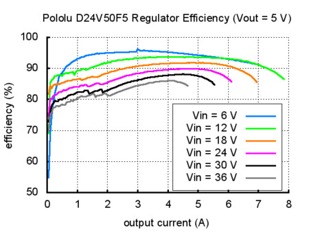
Typical efficiency and output current
The efficiency of a voltage regulator, defined as (Power out)/(Power in), is an important measure of its performance, especially when battery life or heat are concerns. As shown in the graph below, these switching regulators have an efficiency of 85% to 95% for most combinations of input voltage, and load.
The maximum achievable output current of the board depends on many factors, including the ambient temperature, air flow, heat sinking, and the input and output voltage.
During normal operation, this product can get hot enough to burn you. Take care when handling this product or other components connected to it.
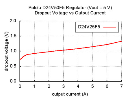
Typical dropout voltage
The dropout voltage of a step-down regulator is the minimum amount by which the input voltage must exceed the regulator’s target output voltage in order to ensure the target output can be achieved. For example, if a 5 V regulator has a 1 V dropout voltage, the input must be at least 6 V to ensure the output is the full 5 V. The following graph shows the dropout voltages for the D24V50F5 regulator as a function of the output current:
Switching frequency and behavior under light loads
The regulator generally operates at a switching frequency of around 600 kHz, but the frequency drops when encountering a light load to improve efficiency. This could make it harder to filter out noise on the output caused by switching.
Write a review
Your Name:
Your Review:
Note: HTML is not translated!
Rating:
Bad
Good
Enter the code in the box below:
-
-80x80.jpg) ₹1,189.00
₹1,189.00
-80x80.jpg)
-80x80.jpg)
© 2025, MG Automation Technologies. Powered by MG Super LABS.Find us on Google+
Designed with by Ish Gupta