Stepper 4 click
Product Code: MIKROE-2748


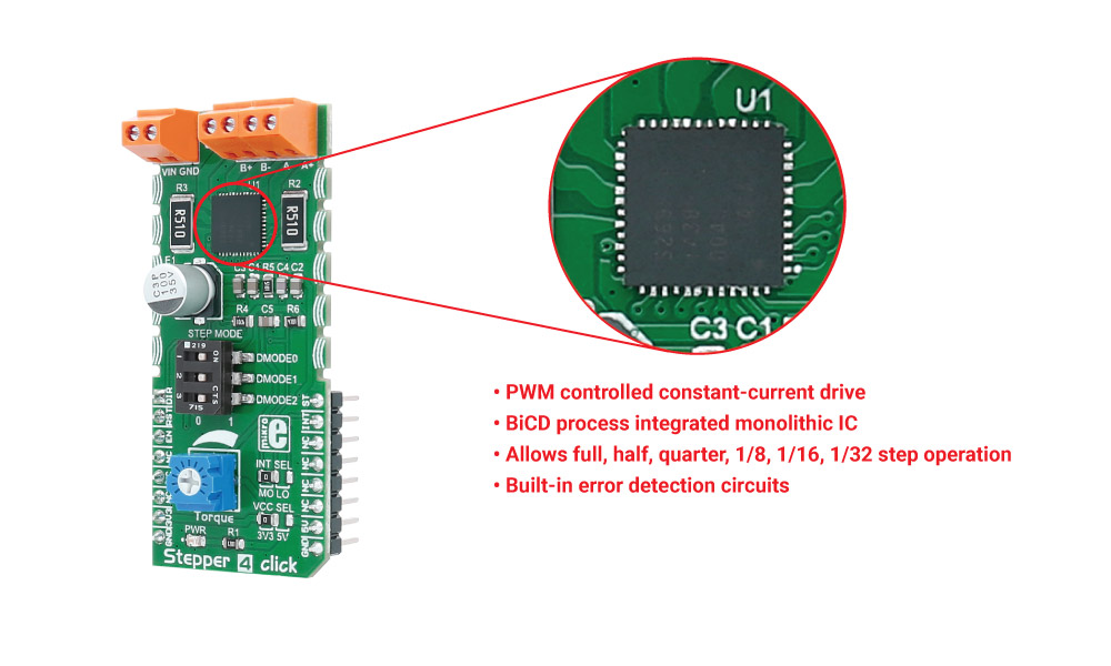
Stepper 4 click carries the TB67S269FTG, a two-phase bipolar stepping motor driver from Toshiba. The click is designed to run on either 3.3V or 5V power supply. It communicates with the target microcontroller over the following pins on the mikroBUS™ line: AN, RST, CS, PWM, INT.
How the click works
There is a connector with two screw terminals used for connecting external DC supply.
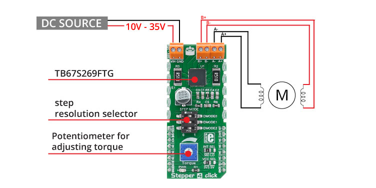
The other four connectors are used for connecting the stepper motor to the click. After a motor is connected, it can be controlled by the MCU through the Stepper 4 click.
The onboard potentiometer is used to set the motor's torque.
TB67S269FTG features
The TB67S269 is a two-phase bipolar stepping motor driver from Toshiba.
Step mode selector
There are several different resolutions a stepper motor can use - a full step, half a step, etc. The driver on this click also allows different resolutions, from a full step to 1/32 of a step.
| DMODE0 | DMODE1 | DDMODE2 | Function |
|---|---|---|---|
| 0 | 0 | 0 | Standby mode (the OSCM is disabled and the output stage is set to ‘OFF’ status) |
| 0 | 0 | 1 | Full step resolution |
| 0 | 1 | 0 | Half step resolution (Type(B)) |
| 0 | 1 | 1 | Quarter step resolution |
| 1 | 0 | 0 | Half step resolution (Type (B)) |
| 1 | 0 | 1 | 1/8 step resolution |
| 1 | 1 | 0 | 1/16 step resolution |
| 1 | 1 | 1 | 1/32 step resolution |
Specifications
| Type | Stepper |
| Applications | The click is designed for driving bipolar step motors in full, 1/2, 1/4, 1/8, 1/16, 1/32 step modes |
| On-board modules | TB67S269FT CLOCK-in controlled bipolar stepping motor driver, three pairs of screw terminals, potentiometer |
| Interface | GPIO |
| Input Voltage | 3.3V or 5V |
| Click board size | L (57.15 x 25.4 mm) |
Pinout diagram
This table shows how the pinout on Stepper 4 click corresponds to the pinout on the mikroBUS™ socket (the latter shown in the two middle columns).
| Notes | Pin | Pin | Notes | ||||
|---|---|---|---|---|---|---|---|
| Rotation direction | DIR | 1 | AN | PWM | 16 | ST | Stepping pin |
| Reset | RST | 2 | RST | INT | 15 | INT | Interrupt |
| Enable pin | EN | 3 | CS | TX | 14 | NC | |
| NC | 4 | SCK | RX | 13 | NC | ||
| NC | 5 | MISO | SCL | 12 | NC | ||
| NC | 6 | MOSI | SDA | 11 | NC | ||
| Power supply | +3.3V | 7 | 3.3V | 5V | 10 | +5V | Power supply |
| Ground | GND | 8 | GND | GND | 9 | GND | Ground |
Jumpers and settings
| Designator | Name | Default Position | Default Option | Description |
|---|---|---|---|---|
| VCC SEL | VCC SEL | Left | 3V3 | Power supply selection, left position 3V3, right position 5V |
| INT SEL | INT SEL | Left | MO | Interrupt pin selection, left position MO, right position LO |
Programming
Code examples for Stepper 4 click, written for MikroElektronika hardware and compilers are available on Libstock.
Code snippet
The following code snippet shows how the Stepper 4 click moves a stepper motor.
Firstly, the speed is set to 400 steps per revolution. Afterwards, the acceleration and the deceleration rate is set. The STEPPER_step method moves the motor a given number of steps. When the number is negative, the motor moves counterclockwise, otherwise, it moves clockwise.
So in this example, it first moves 1000 steps to the left, and then 1000 to the right, at different speeds.
1 void Stepper_4_Task()
2 {
3     STEPPER_setSpeed( 400 );
4     STEPPER_setAcc( 10 );
5     STEPPER_setDec( 5 );
6     STEPPER_step( -1000 );
7     STEPPER_setSpeed( 600 );
8     STEPPER_step( 1000 );
9 }
Downloads
mikroBUS™ Standard specificationStepper 4 click schematic
TB67S269FTG datasheet
Write a review
Your Name:
Your Review:
Note: HTML is not translated!
Rating:
Bad
Good
Enter the code in the box below:
-
 ₹1,999.00


© 2024, MG Automation Technologies. Powered by MG Super LABS.Find us on Google+
Designed with by Ish Gupta