Stepper 6 click
Product Code: MIKROE-3214


The DRV8886 step motor driver IC can deliver a reasonably high amount of current to the connected load. This IC uses a set of I/O pins, simplifying the control over the connected step motor. Since the DRV8886 IC offers so many options, an additional port expander IC is used to cover them all, offering the full control over the IC via the SPI interface, with no restrictions.
The DRV8886 IC also features a full set of protection features: overvoltage, thermal, overcurrent, and undervoltage protection schemes are all present on this IC, along with the fault indication pin. All these features make the Stepper 6 click a robust and versatile bipolar step motor driving solution. With its integrated current sensing, a microstepping ratio up to 1:16, a non-circular stepping mode for higher torque output, a high efficiency, and a reasonably high current it can deliver, the Stepper 6 click is a perfect solution for any application that requires an efficient and reliable motor driver. It can be used in 3D printers, laser printers, laser engravers, video security cameras, factory automatization, robotics, and other similar applications.
How does it work?
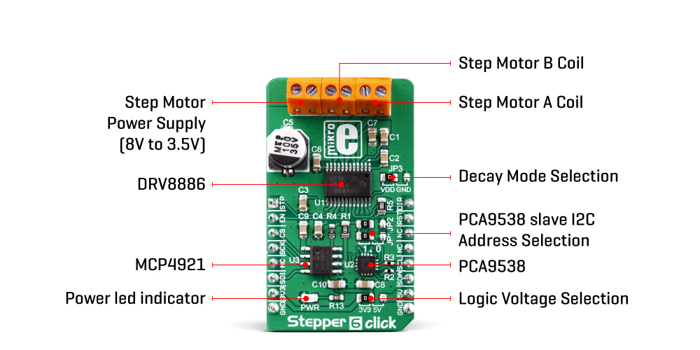
Stepper 6 click is equipped with the DRV8886, a highly integrated bipolar step motor driver with current sensing, from Texas Instruments. This integrated driver offers a simple interface, featuring a set of pins used to control the functions of the step motor. Since the number of pins exceeds the available mikroBUS™ general purpose pins, an additional port expander IC is used, exposing a 2-wire I2C interface for the communication with the host MCU. The port expander IC is the PCA9538, an 8-bit port expander with the I2C interface, an interrupt, and a reset, from NXP.
The high efficiency of the integrated N-Channel power MOSFET H-Bridges allows a high efficiency to be achieved: Stepper 6 click can withstand peaks of current up to 3A, while the internal current limiter is set to 1.4 A per bridge. The Click board™ can work with in the range from 8V up to 35V. However, when operated near the upper current and voltage limits, component heating is expected. If the temperature threshold of 150° is reached, a thermal protection will be engaged, while the fault condition will be indicated with the nFAULT pin of the DRV8886 IC. The nFAULT pin is routed to the port expander IC, allowing its state to be read over the I2C interface. The I2C interface bus of the PCA9538 is routed to the appropriate mikroBUS™ pins (SCA, SDL), allowing the host MCU to control it and read states of its pins.
The PCA9538 is also connected to some other pins: both M0 and M1 pins are routed to this IC, allowing the microstepping configuration over the I2C interface. These two pins are used to set the microstepping size in the range from 1 to 1/6 of a step. The current through the coils is indexed and depends on a position, so the angle of 0° will allow 100% of the current to run through the coil, scaling it down to 0% for the 90°. These current values change with the step position and the microstepping current on an H-Bridge output is a sine function. An additional non-circular half-stepping mode is also available when more torque is required at higher motor RPM. The current in this mode is simply switched from 0% to 100% with no indexed values in between. One of the key features of the DRV8886 IC is the integration of the sensing resistors, which reduces the design complexity.
The current decay through the coil for the circular microstepping modes is controlled by the DRV8886 IC, which offers three different decaying modes: slow decay, slow-mixed decay, and all mixed decay. The correct decay mode is necessary to prevent loss of the current regulation through the coil which might degrade the efficiency of the stepper motor control. The DECAY pin offers the control over the decay mode, and it is routed to the SMD jumper JP3, allowing it to be either pulled up (to the DVDD) or to the GND. The DRV8886 offers detailed information about the decay modes and how to set this pin for each.
The maximum current is limited by setting the current through the RREF pin. A DAC converter is used to set the voltage at this pin. The pin is typically used with the resistor connected to the GND, but the Stepper 6 click uses the MCP4921, a dedicated 12-bit DAC with SPI interface, from Microchip. This way, it is possible to change the maximum current limit by the firmware. The SPI interface of the MCP4921 is routed to the mikroBUS™, allowing the host MCU to take control over the maximum current limit. To find about the current limiting by using the DAC, please visit the DRV8886 datasheet. It offers all the necessary formulas to calculate the required DAC value for a certain current limit. However, the Click board™ comes with the library that contains functions which allow operational parameters of the Click board™ to be forwarded as the simple function arguments.
The maximum current is additionally scaled down by the TRQ pin, which can have three different states. A logic LOW state on this pin will not scale the current limit, at all. A logic HIGH will scale the current limiting factor down to 50%. If the pin is in the HIGH-Z mode (floating), the current limiting factor will be set to 75%. The current limiting formulas in the DRV8886 datasheet do take into the account the scaling factor set by the TRQ pin. This pin is routed to the port expander IC and is available to be controlled over the I2C interface.
The STEP, DIR, and EN pins of the DRV8886 are directly routed to the mikroBUS™ pins AN, PWM, and RST, respectively. These pins comprise the basic stepper motor driving interface, typically used on many similar devices: a rising edge on the STEP input pin will advance the internal sequencer (indexer) for one step; the DIR pin sets the direction, while the EN pin enables the output drives. A LOW logic level on this pin disables the H-Bridges at the output, leaving the logic section operational. A rising edge on the STEP input will still advance the internal sequencer, yet the connected motor will not act, as the H-Bridges are disabled.
Stepper 6 click has additional SMD jumpers that are used to set up the I2C slave address for the PCA9538 port expander (JP1 and JP2), as well as the logic voltage level selection SMD jumper, which allows selecting either 3.3V or 5V, allowing interfacing with a wide range of different MCUs. The motor power supply, as well as the two coils of a bipolar stepper motor (A and B), are connected to the Click board™ via the screw terminal block, according to the labeling on the bottom side of the Click board™, beneath the terminal.
Specifications
| Type | Stepper |
| Applications | A perfect solution for building various applications that require precise and reliable stepper motor control, such as the movement control of beds, heads, and assemblies of various CNC plotting, milling and 3D printer designs, industrial automatization, security cameras… |
| On-board modules | DRV8886, a bipolar step motor driver with current sensing, from Texas Instruments; PCA9538, an 8-bit port expander with the I2C interface, from NXP; MCP4921, a 12-bit DAC with SPI interface, from Microchip |
| Key Features | Integrated current sensing, high efficiency, overcurrent, thermal and undervoltage with fault indication pin, simple motor control interface, up to 1:16 microstepping, wide voltage range, programmatically controlled current limiting, torque scaling, operational mode, step size, and more |
| Interface | I2C,GPIO,SPI |
| Input Voltage | 5V,3.3V |
| Click board size | M (42.9 x 25.4 mm) |
Pinout diagram
This table shows how the pinout on Stepper 6 Click corresponds to the pinout on the mikroBUS™ socket (the latter shown in the two middle columns).
| Notes | Pin | Pin | Notes | ||||
|---|---|---|---|---|---|---|---|
| Step Control | STP | 1 | AN | PWM | 16 | DIR | Direction Control |
| Chip Enable | EN | 2 | RST | INT | 15 | RST | Reset (PCA9538) |
| Chip Select | CS | 3 | CS | RX | 14 | NC | |
| SPI Clock | SCK | 4 | SCK | TX | 13 | NC | |
| NC | 5 | MISO | SCL | 12 | SCL | I2C Clock | |
| SPI Data IN | SDI | 6 | MOSI | SDA | 11 | SDA | I2C Data |
| Power supply | 3V3 | 7 | 3.3V | 5V | 10 | 5V | Power supply |
| Ground | GND | 8 | GND | GND | 9 | GND | Ground |
Onboard jumpers and connectors
| Label | Name | Default | Description |
|---|---|---|---|
| LD1 | PWR | - | Power LED indicator |
| JP1 - JP2 | JP1 - JP2 | Left | PCA9538 slave I2C address selection: left position HIGH (1), right position LOW (0) |
| JP3 | VCC SEL | Left | Decay mode selection: left position – DECAY pin connected to VDD, right position – DECAY pin connected to GND |
| JP4 | V-, V+, L | Left | Logic voltage level selection: left position - 3.3V; right position - 5V |
| TB1 | AOUT1, AOUT2 | - | Stepper motor coil A connector |
| TB2 | BOUT1, BOUT2 | - | Stepper motor coil B connector |
| TB3 | 8 - 35V | - | Stepper motor power supply input |
Stepper 6 click electrical specifications
| Description | Min | Typ | Max | Unit |
|---|---|---|---|---|
| External power supply voltage | 8 | - | 35 | V |
| Motor RMS current [1] | - | - | 1.4 | A |
| Step size (without the interpolation feature) | 1 | - | 1:16 | step |
Note: Power dissipation should be monitored. An additional heat sink might be required for high current operation
Microstep resolution configuration
| Step Size | 1:1 | 1:2 | 1:4 | 1:8 | 1:16 | 1:2 [*] |
|---|---|---|---|---|---|---|
| M0 | 0 | 0 | 1 | Hi-Z | 1 | Hi-Z |
| M1 | 0 | 1 | 1 | 0 | 0 | 1 |
[*] Non-circular mode
Software support
We provide a library for the Stepper 6 Click on our LibStock page, as well as a demo application (example), developed using MikroElektronika compilers. The demo can run on all the main MikroElektronika development boards.
Library DescriptioThe library
y carries everything needed for stepper motor control including speed and acceleration setup. Library is also adjustable to working on different amount of ticks per second, also speed and acceleration can be provided in float format. Buffer used for movement calculation is defined by user so this library can be adjusted for MCUs with very limited RAM resources. Library also offers a choice to choose the stepper working mode and microstep resolution. Check documentation for more details how to use it.
Key functions:
uint8_t stepper6_setSpeed( float minSpeed, float maxSpeed, float accelRatio, T_STEPPER6_OBJ obj )- Setup motor speed
- uint8_t stepper6_setRoute( const uint8_t direction, uint32_t steps, T_STEPPER6_OBJ obj ) - Setup new route
- void stepper6_start( T_STEPPER6_OBJ obj ) - Start motor movement
- uint8_t stepper6_configSet( uint8_t resetSet, uint8_t sleepSet, uint8_t stepMode, T_STEPPER6_OBJ obj ) - Working mode configurations
Examples description
The application is composed of the three sections :
- System Initialization - Initializes all GPIO pins found on Stepper_6 Click and timer to 1ms interrupt.
- Application Initialization - First segment initializes driver, stepper working mode and stepper control. Second segment setup movement limits, maximum and minimum speed, and acceleration ratio. Third segment enables motor and setup new route which will be called from application task.
- Application Task - (code snippet) - Sequentialy moves motor. Executes movement until the end. When movement is finished, waits for two seconds and then repeats all operation.
void applicationTask()
{
   stepper6_start( (T_STEPPER6_OBJ)&myStepper );
   while ( myStepper.status.running )
   {
   stepper6_process( (T_STEPPER6_OBJ)&myStepper );
   }
   Delay_ms( 2000 );
}
In addition to library function calls example carries necessay Timer ISR and Timer initialization. Check
Timer initialization setings and update it according to your MCU - Timer Calculator.
The full application code, and ready to use projects can be found on our LibStock page.
Additional notes and information
Depending on the development board you are using, you may need USB UART click, USB UART 2 click or RS232 click to connect to your PC, for development systems with no UART to USB interface available on the board. The terminal available in all MikroElektronika compilers, or any other terminal application of your choice, can be used to read the message.
mikroSDK
This click board is supported with mikroSDK - MikroElektronika Software Development Kit. To ensure proper operation of mikroSDK compliant click board demo applications, mikroSDK should be downloaded from the LibStock and installed for the compiler you are using.
For more information about mikroSDK, visit the official page.
Downloads
mikroBUS™ Standard specificationStepper 6 click 2D and 3D files
Write a review
Your Name:
Your Review:
Note: HTML is not translated!
Rating:
Bad
Good
Enter the code in the box below:
-
 ₹2,099.00


© 2026, MG Automation Technologies. Powered by MG Super LABS.Find us on Google+
Designed with by Ish Gupta