7inch Capacitive Touch LCD (G) 800 × 480
Product Code: Waveshare 14658
 800 × 480")
 800 × 480")
 800 × 480")
 800 × 480")

Key Parameters
| LCD Type | TFT |
|---|---|
| LCD Interface | 24-bit parallel |
| Touch Screen Interface | 4 wires, capacitive |
| Touch Controller | GT911 |
| Backlight | LED |
| Display Size (mm) | 154.08 (W) × 85.92 (H) |
| Dot Pitch (mm) | 0.0642 (W) × 0.1790 (H) |
| Aspect Ratio | 8 : 5 |
| Resolution | 800 * 480 (Pixel) |
| Power Consumption | TBD |
| Backlight Current | TBD |
| Operating Temp. (℃) | TBD |
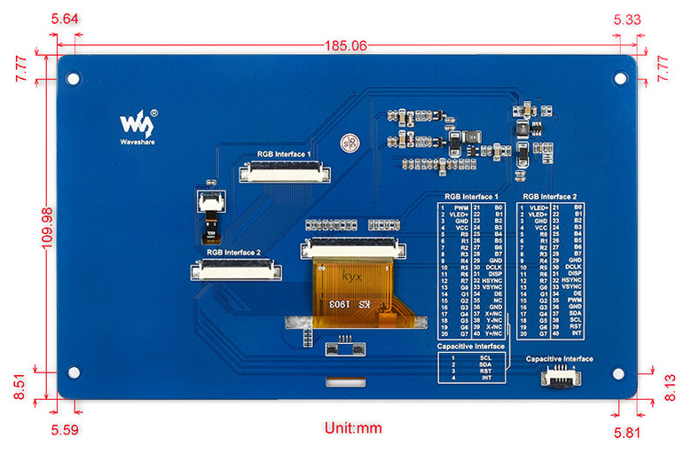
Capacitive Touch Screen Interface Definition
| Pin No. | Symbol | Description | Type | Function |
|---|---|---|---|---|
| 1 | CAP_INT | Interrupt | input | External touch interrupt control input |
| 2 | CAP_WAKE | WAKEUP | input | Used to awake the external TP controller |
| 3 | I2C_SDA | I2C data pin | output/input | Read/Write I2C data |
| 4 | I2C_SCL | I2C clock pin | input | Control I2C clock |
RGB Interface 1 Definition
| Pin No. | Symbol | Description | Type | Function |
|---|---|---|---|---|
| 1 | PWM | Backlight negative | Power | Backlight negative, connects to GND or PWM control |
| 2 | VLED+ | Backlight positive | Power | Backlight positive, 5V typical |
| 3 | GND | Ground | Power | Ground |
| 4 | VCC | Power supply | Power | Power supply, 3.3V |
| 5 | R0 | Data pin | Input | Red data |
| 6 | R1 | |||
| 7 | R2 | |||
| 8 | R3 | |||
| 9 | R4 | |||
| 10 | R5 | |||
| 11 | R6 | |||
| 12 | R7 | |||
| 13 | G0 | Data pin | Input | Green data |
| 14 | G1 | |||
| 15 | G2 | |||
| 16 | G3 | |||
| 17 | G4 | |||
| 18 | G5 | |||
| 19 | G6 | |||
| 20 | G7 | |||
| 21 | B0 | Data pin | Input | Blue data |
| 22 | B1 | |||
| 23 | B2 | |||
| 24 | B3 | |||
| 25 | B4 | |||
| 26 | B5 | |||
| 27 | B6 | |||
| 28 | B7 | |||
| 29 | GND | Ground | Power | GND |
| 30 | DCLK | LCD clock | Input | LCD clock signal |
| 31 | DISP | Enable backlight control | Input | Typically connects to VCC |
| 32 | HSYNC | Horizontal Synchronization | Input | Horizontal synchronous signal input |
| 33 | VSYNC | Vertical Synchronization | Input | Vertical synchronous signal input |
| 34 | DE | Control mode selection | Input | DE = 0 : SYNC mode DE = 1 : DE mode |
| 35 | NC | |||
| 36 | GND | Ground | Power | GND |
| 37 | X+/NC | - | - | NC for capacitive screen |
| 38 | Y-/NC | - | - | NC for capacitive screen |
| 39 | X-/NC | - | - | NC for capacitive screen |
| 40 | Y+/NC | - | - | NC for capacitive screen |
RGB Interface 2 Definition
| PIN NO. | SYMBOL | DESCRIPTION | Type | FUNCTION |
|---|---|---|---|---|
| 1 | VLED+ | Power positive | Power | Backlight power, connects to 5V power supply |
| 2 | VLED+ | |||
| 3 | GND | Ground | GND | |
| 4 | VCC | Power positive | Connects to 3.3V power supply | |
| 5 | R0 | Data pin | Input | Red data |
| 6 | R1 | |||
| 7 | R2 | |||
| 8 | R3 | |||
| 9 | R4 | |||
| 10 | R5 | |||
| 11 | R6 | |||
| 12 | R7 | |||
| 13 | G0 | Data pin | Input | Green data |
| 14 | G1 | |||
| 15 | G2 | |||
| 16 | G3 | |||
| 17 | G4 | |||
| 18 | G5 | |||
| 19 | G6 | |||
| 20 | G7 | |||
| 21 | B0 | Data pin | Input | Blue data |
| 22 | B1 | |||
| 23 | B2 | |||
| 24 | B3 | |||
| 25 | B4 | |||
| 26 | B5 | |||
| 27 | B6 | |||
| 28 | B7 | |||
| 29 | GND | Ground | Power | GND |
| 30 | DCLK | LCD clock | Input | LCD clock signal |
| 31 | DISP | Backlight control enable | Input | Enabled/Disable backlight control |
| 32 | HSYNC | Horizontal Synchronization | Input | Horizontal Synchronization signal input |
| 33 | VSYNC | Vertical Synchronization | Input | Vertical Synchronization signal input |
| 34 | DE | Control mode selection | Input | DE = 0 : SYNC mode DE = 1 : DE mode |
| 35 | PWM | Backlight brightness adjustment | Input | PWM signal for adjusting backlight |
| 36 | GND | Ground | Power | GND |
| 37 | SDA | I2C data | Input/Output | I2C data pin, read/write data |
| 38 | SCL | I2C clock | Input | I2C clock pin |
| 39 | RST | Reset | Input | Reset the TP controller |
| 40 | INT | Interrupt | Output | External touch interrupt |
PACKAGE CONTENT
- 7inch Capacitive Touch LCD (G) x1
- 40-pin FFC x1
- 4-pin FFC x1
External Dimension
Compatibility
The RGB interface 1 is fully compatible with the following product(s):
- 7inch Capacitive Touch LCD
The RGB interface 1 is partially compatible with the following product(s) (only the displaying pins):
- 7inch Resistive Touch LCD
The RGB interface 2 has no FFC connector soldered by default
The RGB interface 2 is compatible with and can be directly connected with the following product(s):
- Open746I
The RGB interface 2 is fully compatible with the following product(s):
- 7inch Capacitive Touch LCD (D)
- 7inch Capacitive Touch LCD (E)
- 7inch Capacitive Touch LCD (F)
- 10.1inch Capacitive Touch LCD (D)
Development Resources
Wiki : www.waveshare.com/wiki/7inch_Capacitive_Touch_LCD_(G)
Write a review
Your Name:
Your Review:
Note: HTML is not translated!
Rating:
Bad
Good
Enter the code in the box below:
© 2026, MG Automation Technologies. Powered by MG Super LABS.Find us on Google+
Designed with by Ish Gupta