AC Current click
Product Code: MIKROE-2523


AC Current click can measure alternating currents up to 30A and it features the MCP3201 ADC (analog to digital) converter and the MCP607 CMOS Op Amp, both from Microchip. The click is designed to run on either 3.3V or 5V power supply. It communicates with the target MCU over an SPI interface, and the AN pin on the mikroBUS™ line.
AC Current click can only be used for sensors with voltage output (30A input current – 1V output voltage amplitude). If someone wants to measure current with a sensor for a different range (10A or 100A), then it is necessary to change the multiplication constant in firmware.
Note: This click board can be used for measuring current from a High-Voltage alternating source, so it is important to know that there is danger from electric shock.
Note: AC Current click does not include the non-invasive AC current sensor. Take a look at the AC Current click - bundle, if you want to buy both the sensor and the click.
MCP3201 ADC converter
MCP3210 ADC converter is a 12-bit Analog-to-Digital converter. The device provides a single pseudo-differential input.
The converter is capable of sample rates of up to 100 ksps at a clock rate of 1.6 MHz. The MCP3201 device operates over a broad voltage range (2.7V-5.5V). Low-current design permits operation with typical standby and active currents of only 500 nA and300 μA, respectively.
MCP607 CMOS Operational Amplifier
MCP607 operational amplifier is unity-gain stable with a low offset voltage (250 μV, maximum). Performance characteristics include rail-to-rail output swing capability and low input bias current (80 pA at +85°C, maximum).
Analog output
There is an Analog output for users who want to side step the onboard ADC and use an ADC from a microcontroller instead.
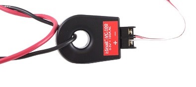
One wire measurement
To measure current using this click it is necessary to put one wire through the sensor, not both.
How it works
When current flows through the sensor there is the same voltage waveform at the output of the sensor (usually sinusoidal).
The first stage on the click board is the Low-Pass filter (whose role is the suppression of radio waves and other noise from large cable from sensor to the click board). The R1 from the Low-Pass filter and the R2 make the voltage divider. After the Low-Pass filter there is the operational amplifier, which is powered by single supply voltage. Because of the single supply this operational amplifier can amplify only the positive part of signal (rectifier). Gain is defined by the R4 and R3:
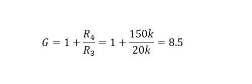
The next stage is another Low-Pass filter which has to make continual DC voltage, which can be used to calculate the input current.
The 12bit ADC is used to convert voltage to digital data. Development board MCU communicates with the ADC using SPI and calculates RMS of input current.
Specifications
| Type | Measurements |
| Applications | One phase measuring from the power line (110/220V) or some other alternating voltage/current source, power consumption measurement, current monitoring (over the analog output). |
| On-board modules | MCP3201, MCP607 |
| Key Features | Non-invasive measurement, 12-bit resolution MCP3201 ADC converter, the click measures alternating currents up to 30A , MCP607 CMOS Op Amp |
| Key Benefits | Non-invasive measurement |
| Interface | SPI |
| Input Voltage | 3.3V or 5V |
| Compatibility | mikroBUS |
| Click board size | M (42.9 x 25.4 mm) |
Pinout diagram
This table shows how the pinout on AC Current click corresponds to the pinout on the mikroBUS™ socket (the latter shown in the two middle columns).
| Notes | Pin | Pin | Notes | ||||
|---|---|---|---|---|---|---|---|
| Analog | AN | 1 | AN | PWM | 16 | NC | |
| NC | 2 | RST | INT | 15 | NC | ||
| Chip select/Shutdown input | CS | 3 | CS | TX | 14 | NC | |
| SPI clock | SCK | 4 | SCK | RX | 13 | NC | |
| Serial data out | MISO | 5 | MISO | SCL | 12 | NC | |
| NC | 6 | MOSI | SDA | 11 | NC | ||
| Power supply | +3.3V | 7 | 3.3V | 5V | 10 | +5V | Power supply |
| Ground | GND | 8 | GND | GND | 9 | GND | Ground |
Onboard jumpers
The table below shows information about onboard jumpers:
| Designator | Name | Default Position | Default Option | Description |
|---|---|---|---|---|
| JP1 | PWR.SEL. | Left | 3.3V | Power Supply Voltage Selection 3.3V/5V, left position 3.3V, right position 5V |
Programming
This code snippet initializes MCU, AC Current click board and measures and shows current value in mA.
01 void main()
02 {
03   system_init();
04   ac_current_init();
05
06   while ( true )
07   {
08     ac_current = 0;
09     ac_current = ac_current_get_mA();
10     usart_write();
11     Delay_ms( 1000 );
12   }
13 }
Downloads
mikroBUS™ Standard specificationAC Current click Schematic
MCP3201 datasheet
MCP607 datasheet
Write a review
Your Name:
Your Review:
Note: HTML is not translated!
Rating:
Bad
Good
Enter the code in the box below:
-
 ₹3,049.00


© 2026, MG Automation Technologies. Powered by MG Super LABS.Find us on Google+
Designed with by Ish Gupta