Arduino MKR GSM 1400
Product Code: Arduino ABX00018


Arduino MKR GSM 1400 has been designed to offer a practical and cost effective solution for makers seeking to add global GSM connectivity to their projects with minimal previous experience in networking. It is based on the Atmel SAMD21 and a SARAU201 GSM module.
The design includes the ability to power the board using a LiPo battery or external power source rated 5V. Switching from one source to the other is done automatically. A good 32 bit computational power similar to the Zero board, the usual rich set of I/O interfaces, gobal GSM communication and the ease of use of the Arduino Software (IDE) for code development and programming. All these features make this board the preferred choice for the emerging IoT battery-powered projects in a compact form factor. The USB port can be used to supply power (5V) to the board. During cellular transmissions the peak current required by the board will exceed 500mA. This is in excess of what can sourced by a standard USB port, so it is MANDATORY to have a 1500 mAh or higher LiPo battery plugged all the time, the current provided by the USB port will be supplmented by the battery. When powering the board using Vin, a 5V power supply that can supply atleast 2A is required..
Warning: Unlike most Arduino & Genuino boards, the MKR GSM 1400 runs at 3.3V. The maximum voltage that the I/O pins can tolerate is 3.3V. Applying voltages higher than 3.3V to any I/O pin could damage the board. While output to 5V digital devices is possible, bidirectional communication with 5V devices needs proper level shifting.
You can find here your board warranty informations.
Getting Started
You can find in the Getting Started section all the information you need to configure your board, use the Arduino Software (IDE), and start tinker with coding and electronics.
Need Help?
- On the Software on the Arduino Forum
- On Projects on the Arduino Forum
- On the Product itself through our Customer Support
Technical Specification
| Microcontroller | SAMD21 Cortex-M0+ 32bit low power ARM MCU |
| Board Power Supply (USB/VIN) | 5V |
| Supported Battery(*) | 3.7V LiPo |
| Circuit Operating Voltage | 3.3V |
| Digital I/O Pins | 8 |
| PWM Pins | 12 (0, 1, 2, 3, 4, 5, 6, 7, 8, 10, A3 - or 18 -, A4 -or 19) |
| UART | 1 |
| SPI | 1 |
| I2C | 1 |
| Analog Input Pins | 7 (ADC 8/10/12 bit) |
| Analog Output Pins | 1 (DAC 10 bit) |
| External Interrupts | 8 (0, 1, 4, 5, 6, 7, 8, A1 -or 16-, A2 - or 17) |
| DC Current per I/O Pin | 7 mA |
| Flash Memory | 256 KB |
| SRAM | 32 KB |
| EEPROM | no |
| Clock Speed | 32.768 kHz (RTC), 48 MHz |
| LED_BUILTIN | 6 |
| Full-Speed USB Device and embedded Host | |
| Antenna power | 2dB |
| Carrier frequency | 433/868/915 MHz |
| Working region | Global |
| Length | 67.64 mm |
| Width | 25 mm |
Documents
OSH: Schematics
The MKR GSM 1400 is open-source hardware! You can build your own board using the following files:
EAGLE FILES IN .ZIPSCHEMATICS IN .PDFFRITZING IN .FZPZ
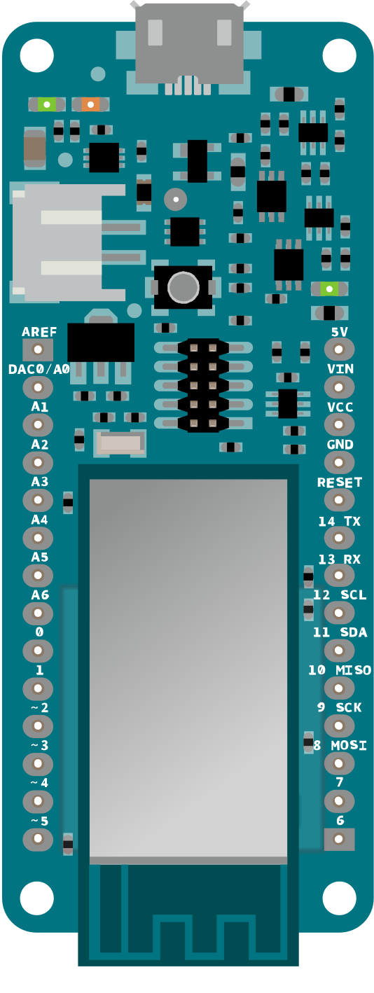
Pinout
Download the pinout in PNG format
Antenna
The MKR GSM 1400 has to be used with a GSM antenna that can be attached to the board with the micro UFL connector. Please check that it can accept frequencies in the GSM's range (880/915 MHz).
Please note: for best result, do not attach the antenna to a metallic surface like car chassis, etc.
Batteries, Pins and board LEDs
Battery capacity: The connected battery must be a 3.7V LiPo
Vin: This pin can be used to power the board with a regulated voltage source rated at 5V. If the power is fed through this pin, the USB power source is disconnected. This is the only way you can supply MAXIMUM 5V to the board not using USB. This pin is an INPUT.
5V: This pin outputs 5V from the the board when powered from the USB connector or from the VIN pin of the board. It is unregulated and the voltage is taken directly from the inputs.
VCC: This pin outputs 3.3V through the on-board voltage regulator. This voltage is 3.3V if USB or VIN is used and equal to the series of the two batteries when they are used
LED ON: This LED is connected to the input voltage source from either USB or VIN. It is also connected to the battery power. This means that it is ON (with a lower intensity) also when the battery is inserted.
Onboard LED: On MKR GSM 1400 the on board LED is connected to D6 and not D13 as on the other boards. Blink example or other sketcthes that uses pin 13 for on board LED may need to be changed to work properly.
Write a review
Your Name:
Your Review:
Note: HTML is not translated!
Rating:
Bad
Good
Enter the code in the box below:
-
 ₹1,319.00
© 2026, MG Automation Technologies. Powered by MG Super LABS.Find us on Google+
Designed with by Ish Gupta