Color 8 click
Product Code: MIKROE-3213


The great precision of color measuring is achieved with features such as the IRCUT filter which reduces the influence of the IR light to non-IR sensing elements, a dedicated IR photosensor, 50/60 Hz noise rejection algorithm, three independent 16-bit A/D converters, and very high color sensitivity with the programmable integrator and gain amplifier.
In addition to high accuracy and sensitivity, this color sensor also offers a programmable interrupt pin, which can be used to trigger an interrupt on the host MCU. This allows a more efficient controller firmware to be written. Features, such as the high dynamic range, programmable gain and integration time, a very high sensitivity, a flexible interrupt engine, and more, make it a very convenient solution for LED lighting color management, TFT display color correction, display color correction on mobile devices, and other similar applications that require an accurate color sensing.
How does it work?
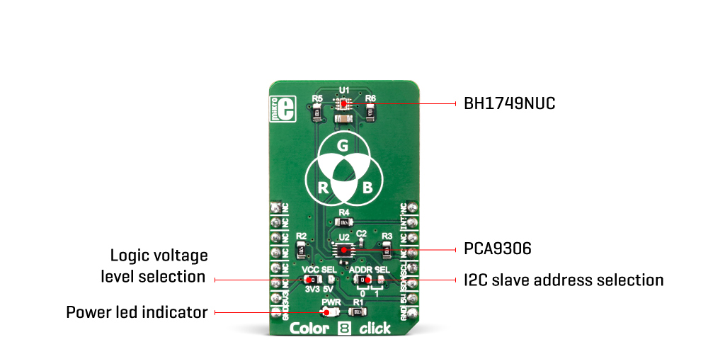
Color 8 click utilizes the BH1749NUC, an integrated color sensor IC, made by ROHM Semiconductor. This highly advanced four-channel color sensing device incorporates an IRCUT filter, that is used to block a portion of light in the IR spectrum, which can interfere with the readings of three independent photo-diodes, used to sense red, green and blue components of the light. However, it features an additional IR photo-sensing element, which is used to detect the intensity in the IR range. The IR measurement value can be used as a compensation parameter for the accurate color calculation.
The color intensity sensing is roughly matched to the sensitivity of the human eye, so the sensor is the most sensitive in the range between 500nm and 600nm. The datasheet of the BH1749NUC offers an intensity over the wavelength diagram, so an accurate color calculation can be made in respect to the variable sensitivity of the sensor over the light wavelength.
There are three independent A/D converters which are used to digitize the color intensity in 16-bit resolution. One of the converters, which is otherwise used for the blue light, is internally multiplexed with the IR photo-diode. A programmable transimpedance gain amplifier (TIA) is available for both the RGB and IR channels, allowing amplification of the signal in the range from 1x to 32x. When using the highest gain ratio, in combination with the longest measurement time, which can be set up to 240ms, it is possible to achieve very high resolution of 0.0125 lx per count. The color and IR conversion results are available at the output registers in MSB/LSB format. Color 8 click communicates with the host MCU over the I2C interface, with its pin routed to the appropriate SCL and SDA pins of the mikroBUS™.
The I2C address can be selected between two possible values: The slave I2C address depends on the state of the ADDR pin: if the pin at LOW logic level (0), the 7-bit I2C slave address is 0x38. If the pin is at the HIGH logic level (1), the I2C address is 0x39. The I2C slave address selection can be done by switching the SMD jumper labeled as ADDR SEL to an appropriate position: left position for logic 0, right position for logic 1.
The powerful interrupt engine allows more optimized firmware for the controller (MCU) to be written. The interrupt engine allows 16-bit values for the upper and lower threshold levels to be defined, as well as the persistence interval during which the event has occurred, before the interrupt is triggered, and more. Also, the user has the possibility to select which channel is included in the interrupt event detection (R, G, or B channel)
The BH1749NUC requires a very low number of external components. It requires only pull-up resistors for the I2C bus lines and the INT pin, which is an open-drain interrupt line. This leaves room for yet another IC. The PCA9306, a bi-directional I2C level translator, from Texas Instruments, is often used in many Click board™ designs, due to its reliability and simplicity. It shifts the voltage levels of I2C and INT lines, thus allowing communication with MCUs that use both 3.3V and 5V as the communication voltage level. By moving the SMD jumper labeled as VCC SEL, it is possible to change the reference voltage for the PCA 9306, effectively changing the voltage level of the communication lines.
Specifications
| Type | Optical |
| Applications | This Click board™ is an ideal solution for LED lighting color management, ambient light sensing for display backlight control, TFT display color control, and other similar applications that require an accurate color and ambient light sensing |
| On-board modules | BH1749NUC, an integrated color sensor IC, made by ROHM Semiconductor; PCA9306, a bi-directional I2C level translator, from Texas Instruments |
| Key Features | High dynamic range, high sensitivity, IRCUT filter reduces influence of the IR spectrum, a dedicated IR photo-diode, powerful interrupt engine, sensitive to IR spectrum, programmable gain and integration time, low number of external components required |
| Interface | I2C |
| Input Voltage | 3.3V,5V |
| Compatibility | mikroBUS |
| Click board size | M (42.9 x 25.4 mm) |
Pinout diagram
This table shows how the pinout on Color 8 Click corresponds to the pinout on the mikroBUS™ socket (the latter shown in the two middle columns).
| Notes | Pin | Pin | Notes | ||||
|---|---|---|---|---|---|---|---|
| NC | 1 | AN | PWM | 16 | NC | ||
| NC | 2 | RST | INT | 15 | INT | Interrupt | |
| NC | 3 | CS | RX | 14 | NC | ||
| NC | 4 | SCK | TX | 13 | NC | ||
| NC | 5 | MISO | SCL | 12 | SCL | I2C Clock | |
| NC | 6 | MOSI | SDA | 11 | SDA | I2C Data | |
| Power supply | 3V3 | 7 | 3.3V | 5V | 10 | NC | |
| Ground | GND | 8 | GND | GND | 9 | GND | Ground |
Onboard jumpers and settings
| Label | Name | Default | Description |
|---|---|---|---|
| LD1 | PWR | - | Power LED indicator |
| JP1 | VCC SEL | Left | Logic voltage level selection: left position 3.3V, right position 5V |
| JP2 | ADDR SEL | Left | I2C slave address selection: left position - address LSB = 0, right position – address LSB = 1 |
Additional specifications
| Description | Min | Typ | Max | Unit |
|---|---|---|---|---|
| ADC Resolution | - | 16 | - | bit |
| Signal Gain Ratio | 1 | - | 32 | X |
| Intensity Detection Range | - | - | 80 | klx |
Software support
We provide a library for the Color8 Click on our LibStock page, as well as a demo application (example), developed using MikroElektronika compilers. The demo can run on all the main MikroElektronika development boards.
Library Description
The library initializes and defines the I2C bus driver and drivers that offer a choice for writing data in register and reads data from register. The library includes function for configuration chip for measurement, function for reads one color and functions for light color value is received by calculating RGB value and conversions in HSL value. The user also has the function color8_getColor() which checks the color of the light.
Key functions:
void float color8_getColorValue()- Functions for read color value in HSL
void uint8_t color8_getColor(float color_value)- Function for set output voltage
Examples description
The application is composed of the three sections :
- System Initialization - Initializes I2C module and sets INT pin as INPUT
- Application Initialization - Initialization driver init and device configuration for start measurement
- Application Task - (code snippet) - Reads RED, GREEEN, BLUE and IR data. Converts data to HSL value and return detect color. For a successful color test, place a click near the color of the monitor and detect the color on the screen.
void applicationTask()
{
    RED_data = color8_readData(_COLOR8_REG_RED_DATA);
    IntToStr(RED_data, demoText);
    mikrobus_logWrite(" RED data : ", _LOG_TEXT);
    mikrobus_logWrite(demoText, _LOG_LINE);

    GREEN_data = color8_readData(_COLOR8_REG_GREEN_DATA);
    IntToStr(GREEN_data, demoText);
    mikrobus_logWrite(" GREEN data : ", _LOG_TEXT);
    mikrobus_logWrite(demoText, _LOG_LINE);

    BLUE_data = color8_readData(_COLOR8_REG_BLUE_DATA);
    IntToStr(BLUE_data, demoText);
    mikrobus_logWrite(" BLUE data : ", _LOG_TEXT);
    mikrobus_logWrite(demoText, _LOG_LINE);

    IR_data = color8_readData(_COLOR8_REG_IR_DATA);
    IntToStr(IR_data, demoText);
    mikrobus_logWrite(" IR data : ", _LOG_TEXT);
    mikrobus_logWrite(demoText, _LOG_LINE);

    colorValue = color8_getColorValue();
    FloatToStr(colorValue, demoText);
    mikrobus_logWrite(" HSL color value : ", _LOG_TEXT);
    mikrobus_logWrite(demoText, _LOG_LINE);

    isColor = color8_getColor(colorValue);

    switch(isColor)
    {
        case 1:
        {
            mikrobus_logWrite("--- Color: ORANGE ", _LOG_LINE);
            break;
        }
        case 2:
        {
            mikrobus_logWrite("--- Color: RED ", _LOG_LINE);
            break;
        }
        case 3:
        {
            mikrobus_logWrite("--- Color: PINK ", _LOG_LINE);
            break;
        }
        case 4:
        {
            mikrobus_logWrite("--- Color: PURPLE ", _LOG_LINE);
            break;
        }
        case 5:
        {
            mikrobus_logWrite("--- Color: BLUE ", _LOG_LINE);
            break;
        }
        case 6:
        {
            mikrobus_logWrite("--- Color: CYAN ", _LOG_LINE);
            break;
        }
        case 7:
        {
            mikrobus_logWrite("--- Color: GREEN ", _LOG_LINE);
            break;
        }
        case 8:
        {
            mikrobus_logWrite("--- Color: YELLOW ", _LOG_LINE);
            break;
        }
        default:
        {
            break;
        }
    }
    Delay_100ms();

    mikrobus_logWrite("  ", _LOG_LINE);
    Delay_ms( 1000 );
}
The full application code, and ready to use projects can be found on our LibStock page.
Other mikroE Libraries used in the example:
- I2C
Additional notes and information
Depending on the development board you are using, you may need USB UART click, USB UART 2 click or RS232 click to connect to your PC, for development systems with no UART to USB interface available on the board. The terminal available in all MikroElektronika compilers, or any other terminal application of your choice, can be used to read the message.
mikroSDK
This click board is supported with mikroSDK - MikroElektronika Software Development Kit. To ensure proper operation of mikroSDK compliant click board demo applications, mikroSDK should be downloaded from the LibStock and installed for the compiler you are using.
For more information about mikroSDK, visit the official page.
Downloads
mikroBUS™ Standard specificationWrite a review
Your Name:
Your Review:
Note: HTML is not translated!
Rating:
Bad
Good
Enter the code in the box below:
-
 ₹2,629.00


© 2026, MG Automation Technologies. Powered by MG Super LABS.Find us on Google+
Designed with by Ish Gupta