Gyro 3 click
Product Code: MIKROE-3449


The I3G4250 IC supports both I2C and SPI interfaces, which allows Gyro 3 click to be interfaced with a wide range of different MCUs. Although it is very sensitive (down to 0.008 dps/LSB) it is very resistant to shock and has a non-linearity of only 0.2% of the full-scale value (FS). These features make Gyro 3 click a perfect solution for the development and testing of a wide range of applications which rely on an accurate angular rate sensing. This includes gyro-stabilization for various types of robots, drones, UAVs and RC vehicles, game controllers, orientation sensing, gesture-based HMI applications, VR glasses, and similar types of applications.
How does it work?
Gyro 3 click is based on the I3G4250, a three-axis digital gyroscope sensor IC, by STMicroelectronics. This device is produced using a proprietary CMOS micromachining technology, which results in a high level of integration, allowing very good linearity over temperature, and increased output stability when no motion applied (referred to as a zero-rate level in the I3G4250 datasheet). It also makes it resistant to shocks, allowing it to be used for speeds up to 2000 dps. It supports signal conditioning including low and high-pass filtering, as well as the threshold detection on each axis.
Typically, higher dps range results in lower sensitivity. Therefore, the I3G4250 allows to dynamically select the full-scale range (FSR) value in several discrete steps: ±245, ±500, and ±2000 dps. This allows optimized performance for a given usage scenario. For example, if used in applications with faster angle rates such as sports equipment monitoring (golf club or tennis racket), a higher FSR might be required, at a cost of lower sensitivity.
The MEMS output voltage is sampled by a high-accuracy 16-bit A/D converter, allowing the output in 2’s complement format. As mentioned above, different FS ranges have different sensitivity per LSB. Therefore, raw output values of the sensor will have to be multiplied with the sensitivity to obtain the values in degrees per second (dps). These values can be obtained from the I3G4250 datasheet, for every FS range, respectively.
There are two filters available on the I3G4250 sensor: an external low-pass (LP) filter, and a digital high-pass (HP) filter with user-selectable cutoff frequency. Both of these signals can be digitally selected and applied to an angular speed measurement, allowing the developer to reduce the noise or fine-tune the sensitivity within a desired bandwidth.
The I3G4250 device features a FIFO buffer, which in combination with a dedicated interrupt line, allows firmware optimizations while reducing the power consumption of the application as a result. The FIFO buffer has 32 slots, each 16-bit wide, used to store output values. The I3G4250 device can be configured to use the FIFO buffer in three different modes: Bypass mode, FIFO mode, and Stream mode. While the first mode allows the developer to read the values directly from the output registers, two other modes allow the utilization of the buffer. The FIFO mode will collect the data and stop collecting until its read (or reset), while the Streaming mode will continuously fill the buffer, discarding the oldest value.
One of the two interrupt lines is labeled as DRDY/INT2 on the schematic, and it is routed to the mikroBUS™ AN pin (labeled as DI2). This line is used to report one of the programmable FIFO events: watermark level is reached, FIFO buffer is empty, and there is an overrun event on the FIFO buffer (FIFO is full). The pin can also be used to report when there is a new data available at the output after the conversion period (data ready). To find out which event exactly has occurred, the host MCU should read the status of the respective flag bits from the STATUS register.
The second interrupt line is used to report when the programmed threshold is reached. It is possible to detect events which are above or below a programmable threshold, and trigger an interrupt on the INT1 pin, routed to the mikroBUS™ INT pin. By directing the I3G4250 device to wait for a built-in timer to expire, a false triggering can be prevented. To detect an interrupt source, the MCU can should read the status of the respective flag bits from the INT1_SRC register.
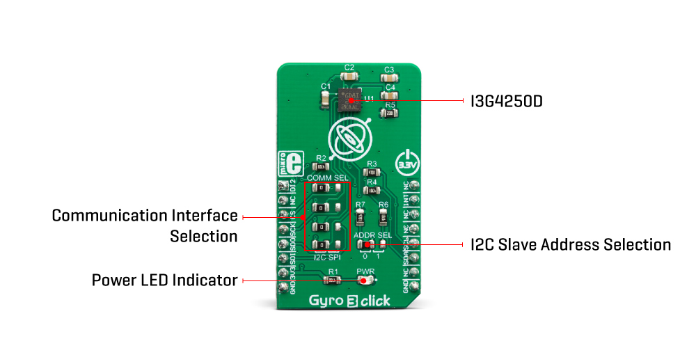
Gyro 3 click offers two communication interfaces. It can be used with either I2C or SPI. The onboard SMD jumpers labeled as COMM SEL allow switching between the two interfaces. Note that all the jumpers have to be positioned either I2C or to SPI position. When I2C interface is selected, an additional SMD jumper labeled as ADDR SEL becomes available, determining the least significant bit of the I3G4250 slave I2C address. The Click board™ should be interfaced only with MCUs that use logic levels of 3.3V.
Specifications
| Type | Motion |
| Applications | It can be used to develop applications for gyro-stabilization of different types of robots, drones, UAVs and RC vehicles, game controllers, orientation sensing, gesture-based HMI applications, VR glasses, and similar types of applications. |
| On-board modules | I3G4250, a three-axis digital gyroscope sensor IC, by STMicroelectronics. |
| Key Features | Advanced interrupt engine allows simplified firmware development and better system-wide power consumption, very good reliability, precision, and zero-level stability, signal conditioning in a form of low and high-pass filtering, both SPI and I2C interface… |
| Interface | I2C,SPI |
| Input Voltage | 3.3V |
| Click board size | M (42.9 x 25.4 mm) |
Pinout Diagram
This table shows how the pinout on Gyro 3 click corresponds to the pinout on the mikroBUS™ socket (the latter shown in the two middle columns).
| Notes | Pin | Pin | Notes | ||||
|---|---|---|---|---|---|---|---|
| INT / Data Ready | DI2 | 1 | AN | PWM | 16 | NC | |
| NC | 2 | RST | INT | 15 | INT | Interrupt | |
| SPI Chip Select | CS | 3 | CS | RX | 14 | NC | |
| SPI Clock | SCK | 4 | SCK | TX | 13 | NC | |
| SPI Data OUT | SDO | 5 | MISO | SCL | 12 | SCL | I2C Clock |
| SPI Data IN | SDI | 6 | MOSI | SDA | 11 | SDA | I2C Data |
| Power Supply | 3.3V | 7 | 3.3V | 5V | 10 | NC | |
| Ground | GND | 8 | GND | GND | 9 | GND | Ground |
Onboard Settings And Indicators
| Label | Name | Default | Description |
|---|---|---|---|
| PWR | PWR | - | Power LED indicator |
| JP1-JP4 | SEL COMM | Right | Communication interface selection: left position SPI, right position I2C |
| JP5 | I2C ADD | Right | I2C address LSB selection: left position 0, right position 1 |
Software Support
We provide a library for the Gyro 3 click on our LibStock page, as well as a demo application (example), developed using MikroElektronika compilers. The demo can run on all the main MikroElektronika development boards.
Library Description
Library contains:
- functions for getting INT and AN pin states.
- function for setting CS pin states.
- functions for getting and setting register values.
- function for getting temperature register value.
- function for getting XYZ-Axes values.
- function for setting basic device parameters.
- function for getting status register value.
- function for getting FIFO data level.
- function for interrupt threshold values and interrupt wait time.
Key functions:
void gyro3_config( void )- sets basic settings to device.void gyro3_getStatus( uint8_t * status_register )- gets value of status register (27h).void gyro3_getAxes( float * x_axis, float * y_axis, float * z_axis, uint8_t measurement_range )- reads values from XYZ-Axes registers and converts them to degrees per second value based on measurement range setting.
Examples description
The application is composed of the three sections :
- System Initialization - systemInit() - Initializes I2C interface, LOG interface and GPIO pins.
- Application Initialization - applicationInit() - Initializes I2C driver and basic device configuratoin.
- Application Task - applicationTask() - Checks if new data is available on all three axes, If yes then reads and logs their values.
void applicationTask( )
{
    gyro3_getStatus( &status_register );

    if ((status_register & _GYRO3_ZYX_NEW_DATA_MASK) == _GYRO3_ZYX_NEW_DATA_MASK)
    {
        gyro3_getAxes( &x_axis, &y_axis, &z_axis, _GYRO3_MEAS_RANGE_2000 );
        mikrobus_logWrite( "rn>>>>>>>>>>>>>>>>>>>", _LOG_LINE );
        FloatToStr( x_axis, text );
        mikrobus_logWrite( "x_axis : ", _LOG_TEXT );
        mikrobus_logWrite( text, _LOG_TEXT );
        mikrobus_logWrite( degrees_per_second, _LOG_LINE );
        FloatToStr( y_axis, text );
        mikrobus_logWrite( "y_axis : ", _LOG_TEXT );
        mikrobus_logWrite( text, _LOG_TEXT );
        mikrobus_logWrite( degrees_per_second, _LOG_LINE );
        FloatToStr( z_axis, text );
        mikrobus_logWrite( "z_axis : ", _LOG_TEXT );
        mikrobus_logWrite( text, _LOG_TEXT );
        mikrobus_logWrite( degrees_per_second, _LOG_LINE );
        mikrobus_logWrite( "<<<<<<<<<<<<<<<<<<<", _LOG_LINE );
    }
    Delay_ms(100);
}
The full application code, and ready to use projects can be found on our LibStock page.
Other mikroE Libraries used in the example:
I2CUARTSPI
Additional notes and informations
Depending on the development board you are using, you may need USB UART click, USB UART 2 click or RS232 click to connect to your PC, for development systems with no UART to USB interface available on the board. The terminal available in all MikroElektronika compilers, or any other terminal application of your choice, can be used to read the message.
MIKROSDK
This click board is supported with mikroSDK - MikroElektronika Software Development Kit. To ensure proper operation of mikroSDK compliant click board demo applications, mikroSDK should be downloaded from the LibStock and installed for the compiler you are using.
For more information about mikroSDK, visit the official page.
Downloads
Write a review
Your Name:
Your Review:
Note: HTML is not translated!
Rating:
Bad
Good
Enter the code in the box below:
-
 ₹2,629.00


© 2026, MG Automation Technologies. Powered by MG Super LABS.Find us on Google+
Designed with by Ish Gupta