RMS to DC click
Product Code: MIKROE-3311


Featuring a very high linearity, a rail-to-rail common mode voltage, a true RMS-to-DC conversion with a minimum number of external components required, an excellent linearity that allows direct application with no compensation elements required, a very wide signal bandwidth, and more, RMS to DC click is an ideal solution for development of various true RMS digital multimeter applications, panel meters and gauges, AC + DC measurement applications, a true RMS measurement of an audio signal and other similar applications that require accurate RMS value readings.
How does it work?
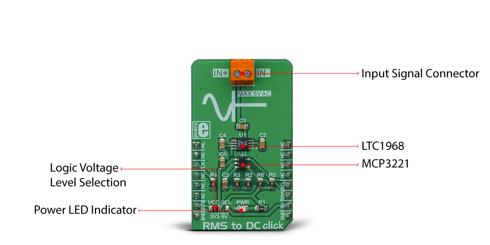
RMS to DC click is based around the LTC1968, a precise RMS-to-DC converter with the wide input signal bandwidth, from the Linear Technology division of Analog Devices. This IC uses the proprietary delta-sigma computational techniques to achieve a highly linear DC voltage output at its output in respect with the RMS of the input signal. The RMS is typically associated with the alternating signals. This Click board™ is capable of measuring the RMS of both bipolar and unipolar periodically alternating signals, over a wide range of frequencies.
The RMS or Root Mean Square is used to describe the power of the input signal: the RMS value of current is equal to a DC current value that would produce the same heat dissipation on the resistive load. Therefore, it is often important to know the RMS value of the signal. RMS to DC click allows measuring of the RMS value of a periodically repetitive signal.
As mentioned before, the LTC1968 provides a highly accurate and linear conversion of the RMS value at its input, to a constant voltage at its output. The constant voltage directly depends on the RMS value of the input signal, thanks to the innovative sigma-delta conversion technique of the LTC1968, which is described in details within the LTC1968 datasheet. Due to a high output voltage linearity, no compensation elements are required, except a single filtering capacitor. The output voltage of the LTC1968 is then fed to an analog-to-digital converter (ADC). For the voltage-to-digital conversion purposes, RMS to DC click utilizes the MCP3221, a 12-bit ADC with I2C interface, from Microchip. This ADC uses the voltage at its power supply pin as a conversion reference. This simplifies the Click board™ schematics, allowing the reference voltage to be changed along with the power supply voltage of the ADC.
The communication logic voltage level, as well as the ADC power supply voltage, can be changed by switching the SMD jumper labeled as VCC SEL to either 3V3 position or 5V position. Note, however, that this will cause the reference ADC voltage to change accordingly. This should be accounted for when calculating the output value.
The input signal can be connected to the two-pole input signal connector. The LTC1968 IC accepts both bipolar and unipolar signals at its input, thanks to the differential input. The negative differential input is used as the reference input on this Click board™, therefore it is offset at 2.5V in respect to GND, while the positive differential input is decoupled by a 100nF capacitor, allowing only the AC component of the input signal to be processed. This allows signal input within the ±2.5 range to be applied.
RMS to DC click also features an #ENABLE pin, used to enable or disable the LTC1968 when used in power sensitive applications. This pin is pulled to a LOW logic level by a resistor, so the IC is enabled by default. The user can disable the IC by pulling the #ENABLE pin to a HIGH logic level. This pin is routed to the CS pin, and it is labeled as EN on this Click board™.
Due to an overall circuit simplicity allowed by the LTC1968 IC, the ADC directly outputs the RMS value of the input signal. However, the Click board™ is supported by a mikroSDK compatible library, which contains functions that simplify the development even further, allowing the RMS data to be read in almost a single line of code.
Specifications
| Type | Measurements |
| Applications | RMS to DC click is an ideal solution for development of various true RMS digital multimeter applications, panel meters and gauges, AC + DC measurement applications, a true RMS measurement of an audio signal and other similar applications that require accurate RMS value readings. |
| On-board modules | LTC1968, a precise RMS-to-DC converter with the wide input signal bandwidth, from the Linear Technology division of Analog Devices; MCP3221, a 12-bit ADC with I2C interface, from Microchip. |
| Key Features | It offers an excellent linearity that allows direct application with no compensation elements required, a rail-to-rail common mode voltage, a true RMS-to-DC conversion with a minimum number of external components, a good thermal stability, a very wide signal bandwidth, and more. |
| Interface | GPIO,I2C |
| Input Voltage | 3.3V or 5V |
| Click board size | M (42.9 x 25.4 mm) |
Pinout diagram
This table shows how the pinout on Thermo 8 click corresponds to the pinout on the mikroBUS™ socket (the latter shown in the two middle columns).
| Notes | Pin | Pin | Notes | ||||
|---|---|---|---|---|---|---|---|
| NC | 1 | AN | PWM | 16 | NC | ||
| NC | 2 | RST | INT | 15 | NC | ||
| LTC1968 Chip Enable | EN | 3 | CS | RX | 14 | NC | |
| NC | 4 | SCK | TX | 13 | NC | ||
| NC | 5 | MISO | SCL | 12 | SCL | I2C Clock | |
| NC | 6 | MOSI | SDA | 11 | SDA | I2C Data | |
| Power Supply | 3V3 | 7 | 3.3V | 5V | 10 | 5V | Power Supply |
| Ground | GND | 8 | GND | GND | 9 | GND | Ground |
Onboard settings and indicators
| Label | Name | Default | Description |
|---|---|---|---|
| PWR | PWR | - | Power LED indicator |
| JP1 | VCC SEL | Left | Power supply voltage selection: left position 3.3V, right position 5V |
| VIN | IN+,IN- | - | Input signal connector |
Software support
We provide a library for the RMS to DC Click on our LibStock page, as well as a demo application (example), developed using MikroElektronika compilers. The demo can run on all the main MikroElektronika development boards.
Library Description
The library performs an RMS to DC signal converting with 12bit resolution. It is also possible to get the averaged output DC signal (voltage), with a minimalized noise. For more details check the documentation.
Key functions:
uint16_t rms2dc_readADC( void )- The function returns a 12bit result of AD conversion.T_RMS2DC_V rms2dc_voutADC( T_RMS2DC_V vccSel )- The function returns the output voltage value calculated to mV, depending on the power voltage selection.T_RMS2DC_V rms2dc_avrgVoutADC( T_RMS2DC_V vccSelect, uint8_t nSamples )- The function returns the averaged output voltage value calculated to mV, depending on the power voltage selection.
Examples description
The application is composed of the three sections :
- System Initialization - Initializes peripherals and pins.
- Application Initialization - Initializes I2C interface and turns ON the device.
- Application Task - (code snippet) - Reads averaged DC output voltage calculated to mV, and sends results to the serial plotter. Note: The input voltage frequency should be in the range from 50Hz to 250kHz. Als,o the input voltage amplitude must be lower than 5V. In these conditions, the device can convert the RMS signal, in every form, to DC signal.
void applicationTask()
{
    outVoltDC = rms2dc_avrgVoutADC( _RMS2DC_VCC_3V3, 25 );

    plotData( outVoltDC );

    Delay_ms( 5 );
}
Additional Functions :
- void plotData( T_RMS2DC_V plotY ) - Sends data (DC voltage) to the serial plotter.
- void logData() - Sends DC voltage value to the uart terminal.
The full application code, and ready to use projects can be found on our LibStock page.
Other mikroE Libraries used in the example:
ConversionsI2C LibraryUART Library
Additional notes and information
Depending on the development board you are using, you may need USB UART click, USB UART 2 click or RS232 click to connect to your PC, for development systems with no UART to USB interface available on the board. The terminal available in all MikroElektronika compilers, or any other terminal application of your choice, can be used to read the message.
Downloads
mikroBUS™ Standard specificationWrite a review
Your Name:
Your Review:
Note: HTML is not translated!
Rating:
Bad
Good
Enter the code in the box below:
-
 ₹1,259.00


© 2026, MG Automation Technologies. Powered by MG Super LABS.Find us on Google+
Designed with by Ish Gupta